SYSCON INPUT MATRICES
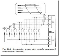
The large number of operating keys associated with modern video- recorders and camcorders necessitates some form of matrixing system to reduce the number of input pins required on the microprocessor. Two approaches are possible, key-scan and A-D conversion. The key- scan method is illustrated in Fig. 16.4, which is taken from a Pana- sonic camcorder. Here IC6003 pulses its key scan ports P00, P01, P02, P03 and P21 at 11 ms intervals, each port having a different pulse timing. When an operation key is pressed one of these scan pulses is fed back into one of the input ports P10–P13 of the same microprocessor IC6003. The micro’s programme now compares output and input pulse timing to detect which button was pressed, and implements its ROM-based operation accordingly. Note the date manipulation keys at left of Fig. 16.4: these commands are routed to an electronic character generator. Five pulse phases and four input ports give a possible total of twenty key combinations, of which fifteen are used here, with only nine lines in the keyboard link. Even greater is the economy of link lines in the A-D converter system.
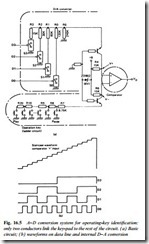
An outline of the principle of a control system using A-D conversion is given in Fig. 16.5. The operation depends on a 4-bit data bus D0–D3 which presents a μP-generated running count of 0–15 in binary terms as shown by the lower waveforms of Fig. 16.5(b). This is applied to a D-A converter consisting of an R/2R network (top of Fig. 16.5(a)) to generate the staircase waveform shown at the top of Fig. 16.5(b): it has sixteen levels ranging from near-zero to near- supply voltage, which might typically be 5 V. This continuous staircase is applied to one input of an op-amp comparator as ‘V+’. Now consider the bottom section of Fig. 16.5(a). Here is a ladder network of resistors with each operation key arranged to ground a section of it. The result is a high voltage at the right-hand side of R7 with no key pressed; and some lower (but closely specified) voltage for each key − ‘play’ may give rise to a voltage of 4.63 V, ‘stop’ 4.25 V and so on, according to the nature of the precision resistor chain R7–R20. This specific ‘function voltage’ is presented to the inverting input of the op-amp comparator.
When any function key is pressed the inverting input of the op-amp moves negatively; output (VD) will rise as soon as the staircase
waveform at its + input permits. This signals to the micro that a command has been keyed in. Acting on this, the micro now resets the data lines D0–D3 to 0000 (VD reverts to low) then increments from 0001 upwards to raise the staircase signal, applied as V+, one step at a time. At some point in the sixteen-step count the V+ input to the op-amp will exceed that of the V– input, whereupon VD will go high once more. The running count is now frozen and examined within the micro. For example, the count may be 1001 which ROM will say corresponds to ‘rewind’. This will then be implemented by the microprocessor, subject to the constraints of deck status sensors. By means of this A−D conversion process, up to fifteen keys can be accommodated by five microprocessor ports, D0–D3 plus switch- data input. The actual keyboard depends on only two connections (V– and ground) provided it incorporates the ladder resistor; this paved the way to providing a full-function corded remote control system using only one pair of conductors in the link-wire – the lad- der resistor is duplicated in the remote handset.

