The sync separator
The purpose of the synchronising separator is to slice the sync pulses off the composite video waveform, separate them into line and field, and feed each one to its individual timebase. The process must be immune to changes in the amplitude and picture composition of the video signal.
As explained in Chapter 1, the sync pulses are arranged to fall beyond the black level and to occupy 30% of the total amplitude of the composite video. A clipping network is therefore all that is required in order to sep- arate the sync pulses away from the video information.
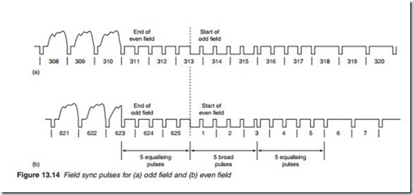
Once the sync pulses have been separated from the composite video, the receiver must be able to distinguish between the two types of sync pulses. While the line sync is represented by a straightforward pulse, the field sync is identified by a series of pulse-width modulated (PWM) wave- form consisting of five consecutive broad pulses at twice line frequency (Figure 13.14). The field flyback lasts for 25 complete lines, giving a total field blanking time of 25 X 64 = 1600 J.s = 1.6 ms. In order to ensure contin- uous line synchronisation throughout the field blanking period, it is nec- essary for line triggering edges to occur where a line sync pulse normally appears. The 2 X line frequency broad pulses ensure this takes place. The extra edges during the field flyback are disregarded by the line oscillator. Before and after the five broad field pulses, five equalising pulses are inserted to ensure good interlacing.
Flywheel sync separator
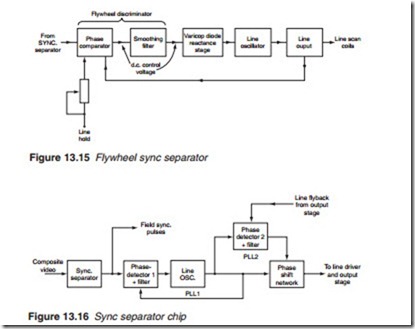
Random pulses due to noise and other interference are sometimes present on the composite video signal. These pulses are similar to the sync pulses themselves and may trigger the timebase at the wrong time. In the case of the field timebase, the integrator which has a slow response removes most of the noise. However, a random pulse occurring near the end of a field causes what is known as frame or field slip. To avoid this, a noise gate (also known as a noise canceller) may be included to obtain a noise-free output from the sync separator. In the case of the line timebase, noise causes what is known as line tearing as some lines are displaced with respect to the oth- ers. On vertical objects, the effect of line tearing is illustrated by ragged edges. Line tearing may be avoided by the use of a flywheel synchronising circuit. The principle of flywheel synchronisation is similar to that of the mechanical flywheel which, due to its large momentum, maintains an aver- age speed unaffected by random changes. The flywheel sync circuit main- tains an average frequency of the sync pulses by monitoring and taking the average frequency of a number of incoming line pulses so that a random pulse will have very little effect on the frequency. A block diagram for a flywheel synchroniser is shown in Figure 13.15. It consists of a flywheel discriminator followed by a reactance stage which controls the fre- quency of the line oscillator. The flywheel discriminator itself consists of a phase comparator or discriminator and a smoothing circuit. A control voltage proportional to the timing, i.e. phase, between the line oscillator and the incoming sync pulse is obtained from the phase comparator. The voltage is then smoothed by the use of a low-pass filter. For good noise immunity, the flywheel discriminator should have slow response, which
means a long time constant for the smoothing circuit so that the average frequency is taken over a large number of line sync pulses. However, the time constant also determines the pull-in range of the flywheel discrimi- nator. The pull-in range is the range of oscillator frequency drift over which the discriminator will pull the oscillator into lock without having to adjust the manual line hold control. A short time constant improves the sensitivity; hence it widens the pull-in range of the discriminator. A com- promise has to be struck so the oscillator has stability within the pull-in range of the discriminator.
Figure 13.16 shows the basic arrangement of a sync processing chip in which PLLs act as flywheel synchronisers. The stability of the line flyback is secured by the use of two PLLs, PLL1 and PLL2. Phase detector 1 com- pares the phase of the square wave output of the line oscillator with the line sync from the sync separator, so it ensures the line oscillator is run- ning at the correct frequency and phase. The second phase detector com- pares the phase of the line oscillator with the line flyback pulse from the line output stage. Any phase error is then corrected by the phase shift net- work which is in essence a PWM that changes the width and hence the phase of the line oscillator square wave output. An additional third PLL who can see the rainbow effect, it is so distracting that it renders the pic- ture literally unwatchable. Others report being able to see the rainbow artefacts on occasion, but find that they are not particularly annoying and do not inhibit the enjoyment of the viewing experience.
TI and the vendors who build DLP-based projectors have made strides in addressing this problem. The first-generation DLP projectors incorpo- rated a colour wheel that rotated 60 times per second, which can be des- ignated as 60 Hz, or 3600 RPM. So with one red, green and blue panel in the wheel, updates on each colour happened 60 times per second. This baseline 60 Hz rotation speed in the first-generation products is known as a ‘1X’ rotation speed.
Upon release of the first-generation machines, it became apparent that quite a few people were seeing rainbow artefacts. So in the second-generation DLP products the colour wheel rotation speed was doubled to 2 X at 120 Hz or 7200 RPM. The doubling of the colour refresh rate reduced the time between colour updates, and so reduced or eliminated the visibility of colour separation artefacts for most people.
Today, as noted above, many DLP projectors being built for the home theatre market incorporate a six-segment colour wheel which has two sets of red, green and blue filters. This wheel still spins at 120 Hz or 7200 RPM, but because red, green and blue are refreshed twice in every rotation rather than once, the industry refers to this as a 4X rotation speed. This further doubling of the refresh rate has again reduced the number of peo- ple who can detect them.
For the large majority of users the six-segment, 4X speed wheels have solved the problem for home theatre or video products. Meanwhile, due to the higher lumen output requirements for business presentation use, most commercial DLP units still use the four-segment, 2X speed wheels.

