The complete DCT coder
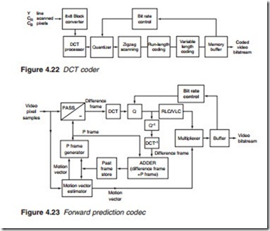
Figure 4.22 shows a block diagram of a basic DCT coder. Luminance or chrominance frame pixel values are first converted from line scan to 8 X 8 block scan before each block is transformed into a DCT matrix of 8 X 8 coefficients. The coefficients are quantised into a number of quantum levels, determined by the bit rate control, and then scanned to produce a stream of 8 X 8 = 64 DCT coefficients for each block. This is followed by RLC and VLC. The compressed bitstream is then fed into a RAM buffer. The resulting bit rate can be varied by the broadcaster at will. This is carried out by sim- ply adjusting the bit rate control. If the output bit rate is reduced to say VHS quality from standard broadcasting PAL quality, there will be fewer quanti- sation levels with the subsequent deterioration in picture quality. However, more programmes may then be squeezed into a single RF channel.
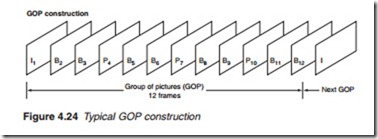
An MPEG-2 coder (which embodies a decoder, hence the name codec) using forward prediction is shown in Figure 4.23. P-coded frames in a group of pictures may be obtained by using an I-frame or a reconstructed
frame as the reference frame. The past-frame memory store must there- fore be continually updated as the pictures in the GOP arrive, frame by frame. The video input, consisting of Y, CR and CB pixel sample values, first enters a memory buffer to be fed into the codec, frame by frame as required. Each frame is identified as a Y, a CR or a CB as well as an I- or P- frame in a group of pictures.
For the I-frame, which cannot be compared with previous frames and hence can suffer only DCT compression, the pixel samples bypass the comparator and go directly to the DCT encoding section to produce a spa- tially compressed DCT frame. The quantised DCT coefficients form the only input to the multiplexer since there is no motion vector. The DCT coefficients are also fed into an inverse quantiser (Q-1) and an inverse DCT (DCT-1) decoder to reconstruct the picture back to its original pixel format in exactly the same way as at the receiver. The reconstructed frame is the only input to the adder since there is no motion vector generated by the I-frame. The reconstructed frame is then saved into the past-frame memory store. When the next picture frame arrives, it is first fed into the motion vector generator. At the same time, the I-frame stored in the past- frame memory is made available to the motion vector generator to pro- duce a motion vector for the frame.
The motion vector is then fed into the P-frame generator. At the same time, the saved I-frame is made available to the P-frame generator. A predicted P-frame is therefore produced which takes two separate paths. One path leads to the comparator unit (with subtract selected) to produce a difference frame or residual error, which after DCT, quantisation and RLC/VLC is fed into the multiplexer. The second path takes the P-frame to the adder to reconstruct the current (second) picture frame and save it in the past-frame memory store to be available for the processing of the next (third) frame. The third frame will follow the same process as the second except that the saved frame, which is used to generate the motion vector and the P-frame, is the frame that has been stored in memory during the processing of the previous frame, namely a P-coded picture frame, and so on to the end of the group of pictures.

