The front end
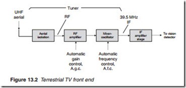
The component parts of the front end of an analogue terrestrial television are shown in Figure 13.2. It consists of the tuner and the IF amplifier stage. The function of the tuner is to select a TV channel frequency, amplify it and convert it into an IF for further amplification by the IF stage. The tuner must be capable of selecting any channel from bands IV and V, and it must provide sufficient RF amplification with good signal-to-noise ratio (SNR) and minimal frequency drift. One or more stages of RF amplification are therefore necessary before the mixer-oscillator stage. A high-pass filter is normally used at the input to the RF amplifier to produce a correctly shaped response curve. The mixer-oscillator changes the tuned RF to a common IF of 39.5 MHz. The tuner unit is built inside a metal case to screen it from outside RF interference. Further screening is also provided between various stages of the unit by metal walls. These inner walls which form part of the tuned circuits prevent unwanted coupling between one
compartment and another. But when a coupling capacitance is needed, a small hole or slot may be cut in the dividing wall.
Both the RF amplifier and RF oscillator use LC tuned circuits. Given the resonant frequency of a tuned circuit
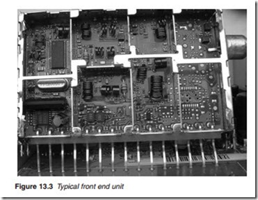
f =1/2n LC and the very high carrier frequencies (370–862 MHz) to which the tuned circuits must resonate, the values of L and C has to be so small as to make it impractical to use normal inductors and capacitors. Instead, transmission lines, normally a quarter of a wavelength long, known as lecher lines are employed in combination with a tuning capacitor. Coupling between stages is achieved by simple loops of wire or by tapping the lecher line. Figure 13.3 shows a typical front end unit incorporating the tuner and the IF stage, all within a single metal case.
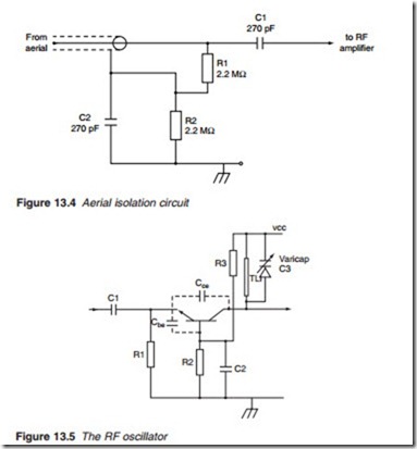
The aerial is usually connected to the tuner via an isolating circuit. This is essential in receivers operating from the mains supply that do not use an isolating transformer. If the receiver is fed directly from the mains, the chassis can become live; and if a live chassis were connected directly to the aerial, it would make the aerial live as well. A commonly used aerial isolation circuit is shown in Figure 13.4. Capacitors C1 and C2 are large enough to give adequate coupling for radio frequencies, but of high enough impedance at the mains frequency of 50 Hz (or 60 Hz) to effectively isolate the aerial from the mains supply. Resistors R1 and R2 prevent static charge from building up on the aerial.


