Raster geometry
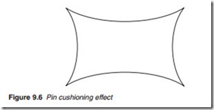
A pure sawtooth scan waveform would produce what is known as ‘pin- cushion’ distortion in a flat or nearly flat screen tubes. This is because an equal angular deflections of the beam scans a smaller distance near the centre of a flat screen compared with the distance it scans further away. A similar effect is produced for the vertical scan. When both non-linearities are considered together, the raster produced on a flat screen exhibits the pincushion distortion illustrated in Figure 9.6. Such distortion may be reduced by the design of the scan coils and to a larger extent by ‘distort- ing’ the shape of the scanning waveform by introducing a non-linearity as a counter balance to the non-linearity of the display, a process known as S-correction. An old technique is the use of small peripheral permanent
magnets placed on the scan coils which may be manually manipulated to obtain the necessary modification of the magnetic field.
Scan velocity modulation
As the electron beam in a CRT display unit retraces the image, line by line across the screen, details and definition may be lost when the scene includes transitions from dark to light, i.e. black vertical edges. Such edges become soft and diffused. Scan velocity modulation, or velocity modulation (VM), attempts to overcome this by emphasizing the edges to improve sharpness. This may be desirable with analogue television and low-resolution video from VCRs. However it is not necessary for high-resolution videos sources such as HDTV and DVD and it must be switched off for these applications to prevent the inevitable artifacts from degrading the picture quality.
VM regulates the speed by which the electron beam scans the screen, hence the name scan velocity modulation. The VM circuit examines the luminance signal and where transition from light to dark area is detected; the beam is slowed down before the transition and speeded up during it. When the beam is slowed down it spends more time writing the light area and the phosphor receives more energy and hence increased brightness and vice versa. This results in an enlarged or ‘enhanced’ black edge. Although this technique remains controversial as far as picture quality is concerned, it has been adopted by many manufacturers and has been promoted as ‘picture enhancement’.
