SIDEBANDS
In an a.m. transmission system sidebands are generated, taking the form of a ‘spreading’ of the carrier wave on each side of its nominal frequency. The extent of these sidebands depends on the frequency of the modulating signal. In an a.m. radio transmission sidebands are present on both sides of the carrier so that the total bandwidth of the transmission (and the spectrum space taken up) equals twice the highest audio frequency used. A simple r.f. modulator as fitted to home videorecorders operates in the same way, producing a double-sideband negatively modulated UHF carrier signal, which for a full-bandwidth (5.5 MHz) vision signal will spread itself over more than 12 MHz of the UHF band.
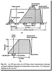
The requirements of a national television service make it necessary to use the available frequency band as effectively as possible, and this has led to the use of vestigial sideband working. Since the information in the upper and lower sidebands is the same, it is theoretically necessary to transmit only one set of sidebands. Single sideband television transmission would, however, lead to great difficulties in the design of transmitter and receiver. An acceptable compromise is found in the vestigial sideband system, where one set of sidebands is partially suppressed. As an example, Fig. 2.6(a) shows the channel 23 sound and vision bandwidths, with a vision carrier
frequency of 487.25 MHz. As can be seen, double sideband transmission of the video signal is retained up to 1.25 MHz on each side of the carrier frequency, but vision frequencies above 1.25 MHz are transmitted on the upper sideband only. In this way the total bandwidth required for the vision and sound signals and guard bands is reduced to 8 MHz.
Vestigial sideband transmission means that the energy in the vision signals received is doubled for frequencies up to 1.25 MHz. To re-balance the energy distribution in the demodulated video signal the pre-detector response curve of the receiver’s signal amplifier is arranged to follow the shape of Fig. 2.6(b). Here the response at the vision carrier frequency is one-half (i.e. 6 dB down) that at higher frequencies. This will be examined more closely in the next chapter.
DIGITAL TV TRANSMISSION
The very different vision and sound modulation and transmission standards used for DTV broadcasts will be dealt with in Chapter 12. Channel allocations and transmitting sites are listed later in this chapter.
TERRESTRIAL DIGITAL TV
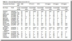
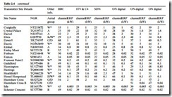
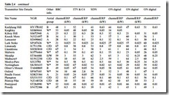
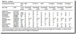
Table 2.4 gives details of UK transmitting sites for DTV. There are six multiplexes, each occupying a conventional 8 MHz TV channel and typically containing five different services. The multiplexes and their operators are as follows: BBC; ITV/CH4; Multiplex A, which is run by SDN Ltd for S4C, C5 and others; and Multiplexes B, C and D, operated by ONdigital. The listing is subject to revision.
TV SOUND TRANSMISSION
The sound that accompanies TV transmissions is better than the audio system and loudspeakers of many TV sets (and VCRs using longitudinal sound recording systems) can do justice to, though contemporary high-quality TV sets and videorecorders are much bet- ter, thanks to the use of large loudspeakers and Hi-Fi sound record- ing techniques respectively. In many countries broadcast TV sound is still monaural. It is (except for French System L) transmitted by frequency modulation (f.m.) of its own carrier wave, whose spacing above the vision carrier frequency varies with the transmission system in use. These systems are summarised in Table 2.9 where it can be seen that for the UK System I the sound-to-vision carrier spacing is 6 MHz. Frequencies up to 15 kHz are transmitted on a carrier whose power is 10% of that of peak vision power. Peak sound carrier deviation is ± 50 kHz, and to reduce the effect of noise a pre-emphasis characteristic corresponding to a time constant of 50 μs is introduced at the transmitter.
STEREO-SOUND TV TRANSMISSIONS
Although stereo sound transmissions have long been established on the Band II VHF radio network, they have now become common as an accompaniment to TV broadcasts. Satellite TV transmission systems (see later) have designed-in provision for stereo sound.
So far as terrestrial TV transmitters are concerned, the pilot-tone systems used for stereo radio are impractical due to their vulner- ability to interference from the vision signal. Alternative systems are in use in Japan (FM-FM system, with subcarrier based on 2 f h carrying a frequency-modulated L−R signal); and Germany, where a second sound carrier, spaced 240 kHz from the main (L + R) sound carrier, conveysa2R signal.
The advance of digital IC technology and the low cost (in mass- production) of sophisticated processing chips has made practical the use of digital sound systems in domestic equipment. Examples of this will be found in the later sections of this book dealing with MAC, Nicam, Video Disc and Hi-Fi videorecorder sound systems.
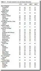
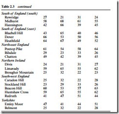
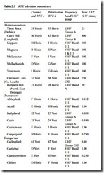
Broadcast TV takes place in the VHF (Bands I and III) and UHF (Bands IV and V) spectra for terrestrial transmitters. In the UK it is currently confined to UHF, with a network of 51 main stations (Fig. 2.7) and about 1000 relay stations, the latter acting as transponders in that they receive signals from the nearest main transmitter and rebroadcast them locally on different channels. The signals from main transmitters are horizontally polarised while those from relays are with a few exceptions vertically polarised, requiring corresponding orientation of the rods of receiving aerials. Each transmitting site is shared by the two broadcasting authorities BBC (transmitters oper- ated by CTI, Castle Transmission International) and ITV so that a single receiving aerial will receive all four transmissions BBC 1, BBC 2, ITV and Channel 4 from the single transmitting array. The details of main transmitters for the UK are given in Table 2.3, and those for Eire in Table 2.5. The Irish broadcasting authority Radio Telefis Eireann (RTE) provides two channels RTE1 and RTE2, some of which
are radiated at VHF as Table 2.5 shows. Irish receivers, then, need to be equipped with both VHF and UHF tuners though at any given receiving site only one band will be in use with an appropriate aerial. The TV broadcast bands are divided into channels, which for System I countries are 8 MHz wide to provide a small guard band between them. The channel frequencies for sound and vision for the UK and Eire are given in Table 2.6, though the VHF channels are not used for TV in the UK. The transmission channels and polarisation of each transmitter in the network is very carefully worked out to provide minimum mutual interference to receivers, and except in unusual barometric conditions the plan works very well. UHF receiving aerial groups and their colour coding is given in Table 2.7.
