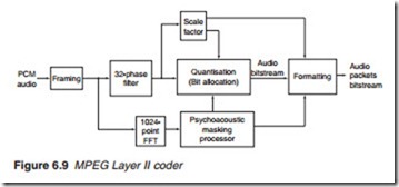
The full Layer II audio coder
Analogue audio L and R channels are sampled separately at a predeter- mined sampling rate. The samples are then encoded as a PCM stream, which is used for MPEG audio encoding (Figure 6.9). Before MPEG coding, the stream is organised into the basic PCM frames of 1152 samples. These frames are then filtered into 32 frequency sub-band blocks, each containing 1152/32 = 36 samples. This is the basic encoding audio blocks. The audio sub-band blocks take two different paths: one path examines the individual blocks and allocates a scale factor for companding purposes. The second path takes the PCM audio stream to the quantiser which carries out its bit allocation function in accordance with the mask- ing algorithm from the psychoacoustic processor. The FFT processor pre- pares a spectral analysis of the PCM input for the masking processor. The masking processor removes redundant audio components and sets the quantising levels for the remaining audio samples. The companded audio samples are then re-quantised in accordance with the bit allocation set by the masking threshold processor to generate a fixed bit rate bitstream. Both the scale factor and the bit allocation are varied as necessary to main- tain a constant bit rate at the output. The bitstream by itself does not contain sufficient information for the receiving end to decode the audio signals. Information about the sampling rate, scale factor and bit allocation has to be included with each coded audio bitstream, along with a variety of other data. This information is incorporated within the audio packet produced by the formatting block.
Layer III coding
The MPEG-2 Layer III (MP3) coding structure retains the 1152-sample frame size and the 32-phase sub-band filter. However, the output from the filter is further processed by modified discrete cosine transform (MDCT)
processor. The main purpose of MDCT is to compensate for some of the filter bank deficiencies mentioned earlier.
MP3 specifies two different size overlapping MDCT windows: a long window with 1152 Samples and a short window of 384 samples as shown in Figure 6.10. The overlap is 50% which means that the number of samples
per window is actually 1/2 X 1152 = 576 and /2 X 384 = 192 for the long and short windows. Given the 32 sub-bands from the filter bank, the number of samples per sub-band is 576/32 = 18 samples or 1152/32 = 36 with 50% overlap and 192/32 = 6 sample or 384/32 = 12 with 50% overlap for long and short windows, respectively. Note the short block length is one third that of a long block. In the short block mode, three short blocks replace a long block so that the number of samples for a frame of audio samples is unchanged regardless of the block size selection. For a sampling frequency of 48 kHz, the lengths of the respective windows are 1152/48 = 24 ms and 384/48 = 8 ms. Switching between the long and short windows decreased the frequency resolution by a factor of 3 but increases the temporal or time resolution by the same factor. The long block is used for audio signals with stationary or periodic characteristics while the short block option is used in blocks containing transients which require better time resolution.
Pre-echo
The combination of band coding and window size causes a strange phenomenon known as pre-echo which is not removed by switching win- dow sizes. Consider a transient occurring towards the end of a block.
Quantising will take account of this and set the quantisation level for the whole block to a higher level than without the transient. Quantising noise will occur at the beginning of the block which is audible before the tran- sient itself, hence the name pre-echo. Pre-echo is eliminated by the use of the buffer shown in Figure 6.11.

