SATELLITE RECEIVING ANTENNAS
Even though the broadcast signal from a satellite is concentrated into a narrow and relatively powerful beam, it cannot be usefully intercepted by a dipole in the same way as longer-wavelength signals. It is necessary, then, to use a large-area collector of SHF signals in the form of a dish or plate to increase the capture area. Most common is the dish aerial in which a parabolic reflector concentrates the signal beam onto a tiny metal patch or probe inside the low-noise- block (LNB) at the focal point of the dish, Fig. 4.5(a). Manufacture and handling of the dish is crucial because its surface must be true enough to ensure in-phase arrival of all the SHF carrier cycles at the pick-up point.
Practical satellite dishes do not have to be completely parabolic in shape: it is sufficient for them to take the form of a section of a parabola so long as the LNB is at the effective focal point. The offset dish, shown in Fig. 4.5(b), is used for domestic reception; it has the two advantages of keeping the LNB’s ‘shadow’ out of the path of incoming signals, and presenting a more nearly vertical face from
which water and snow easily fall away. There are other dish configurations, one of which has the LNB at the rear of the dish, looking at a subreflector at the main focal point.
Dish gain and efficiency
A typical efficiency figure for a receiving dish is 60%. The gain increases with dish size, of course, and the larger the dish the better the received signal. Dish size is a compromise between many factors; for aesthetic, economic and physical reasons home-mounted dish antennas need to be as small and unobtrusive as possible. A large dish has the advantages of providing a greater margin to accommodate losses due to rain, snow and gradual deterioration of efficiency in the system; and a narrower beamwidth, giving greater immunity from interference by other satellites in the burgeoning Clarke belt. It is, however, marginally more difficult to install, more obtrusive, and imposes more strain on its mountings in high winds. The continuing improvement in LNB noise figures has made it possible to use smaller dishes to achieve the required carrier/noise (C/N) ratio, and the greater the EIRP (Effective Isotropic Radiated Power) of the satellite on which it is targeted, the smaller the dish needs to be. In general, dishes of less than 40 cm effective diameter run the risk of picking up interference from other satellites. Thus it is unlikely Mwith current technology that the norm will be less than 40 cm.
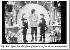
Rain or snow in the air tends to absorb microwave radiation, and short-term signal losses of 3–10 dB can be experienced in heavy weather. In an average installation very heavy rain will reduce the C/N ratio below the system’s noise threshold, the effect of which is sparklies (black and white horizontal dashes) superimposed on the picture. Seldom in Europe or North America does it rain hard enough or long enough for this to be a significant problem, however.
For fixed-dish installations, manufacturers generally provide a complete kit consisting of antenna, LNB, mountings and receiver, all matched to a specific satellite whose EIRP is well established and defined. Used together, the components of such a kit work well so long as the installation is correctly done and the maker’s recommendations of dish-size/LNB specification for different geographical areas is followed. If, however, it is required to mix head-end components of different makes; to match two LNBs to a single dish; to receive low-power or footprint-margin transmissions; or to install a polar-mounted dish other than a custom-made outfit, it is necessary to take into account many factors when specifying the dish, LNB and receiver. This is called a linked budget calculation, covered (with computer program details) in Newnes Guide to Satellite TV by D. J. Stephenson.
Dual-feed systems
There are several forms of dual-feed system for satellite reception from a single dish. Where two or more receivers share a dish a dual- LNB can be used, enabling each viewer to select the programmes required in respect of their polarisation. For MATV installations this type of LNB is also used, here to provide separate feeds of horizontally and vertically polarised signals for amplification and splitting in a distribution amplifier.
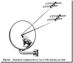
Where reception from more than one satellite is required there are several choices. The simplest and most reliable is the dual-LNB arrangement shown in Fig. 4.6. Here a special bracket supports two LNBs which face the dish at different angles, typically about 6° apart for reception from the Astra (19.2°E) and Eutelsat (13°E) birds. With the dish aligned on the mid-point between them, each satellite’s signal beam is seen only by its ‘own’ LNB due to their different reflection angles and thus each downlead conveys the signals from its own satellite, generally to a receiver with two LNB input sockets and auto- selection of the feed required. An alternative to this is the motorised LNB, which is driven across the face of the dish to ‘see’ any point in a narrow arc of the Clarke belt, narrow because the efficiency of the dish as a reflector drops off sharply a few degrees off centre.
Further choices for multi-satellite reception are a wide-arc dish with several LNBs mounted on a curved boom in front of it, an exten- sion of the set-up illustrated in Fig. 4.6; and a motorised dish on a polar mount, in which the whole assembly, single LNB included, is driven from horizon to horizon (H-H) if required, under the control of the viewer and a computerised auto-seek system. More details of polar mounts and motor-driven dishes are given in Newnes Guide to Satellite TV.
Beam width
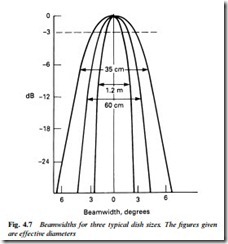
The beamwidth of a dish is inversely proportional to its size, whether it is transmitting or receiving. Footprint shapes and sizes are wholly determined by the design of the satellite-mounted dish, which is ‘fine- tuned’ to give the coverage required by the broadcaster in terms of countries and areas – see Fig. 4.1. Regardless of which end of the chain a dish may be, the beamwidths are represented by cones of 2° angle for 1 m types, 3° angle for 50 cm, and 4.5° angle for 35 cm. The angles are based on half-power (–3 dB) points as shown in Fig.
4.7. there are also side-lobes (not shown in the diagram) on each side of the main aiming path, but their response is typically 20 dB down on the main beam, so they are less likely to contribute interference than to increase the noise component of the received signal. The nature of the spurious lobes depends greatly on the type and design of the dish and LNB unit.
The arbiter of reception quality is the carrier-to-noise ratio. A C/N ratio of 10 dB gives satisfactory results, but leaves little safety margin. We may regard 11 dB as a norm for currently available equipment, and 13.5 dB or more is excellent. As the C/N ratio decreases, there is little effect on the picture until the threshold level of the receiver’s
f.m. vision demodulator is reached, when sparklies begin to intrude on the picture. With terrestrial-type (e.g. PAL, NTSC) colourencoding systems the interference is most obtrusive on highly coloured areas of the picture. As LNB noise figures and carrier detec- tor designs improve, the required C/N ratio becomes less. An off- screen picture of sparklie interference is shown in Fig. 4.8.
Environment-friendly dishes
The fact that (in the northern hemisphere) satellite receiving anten- nas have to point south means that the physical positioning of a home dish is seldom a matter of free choice, though a great deal can be done to hide or disguise the antenna with careful thought and choice of type. Where the dish has to be visible, there are three ways in which its obtrusiveness can be reduced: by painting, by making the dish transparent, and by using an open-mesh construction.
Any conventional dish type can be painted – ideally with spray application – to make it merge into the background against which it is seen. Some dishes come in a choice of colours, but it is generally
necessary to spray the dish after installation, giving a thin and even coat of matt or eggshell-finish paint.
Glass dishes use metallised armoured glass with 99% reflectivity to microwave radiation. They are more expensive than the simplest (pressed sheet metal) types, but are more rigid, reflect less heat onto the LNB assembly, and of course are less obtrusive.
The reduction of visual impact represented by a mesh dish (they are usually black) is somewhat questionable, but they are established in production. Their weight and wind-resistance is less than that of conventional types for a given size, and the perforations have little or no effect on their efficiency. They tend to be more flexible, however, which can be detrimental in high winds.
Flat-plate antennas
An alternative to the parabolic dish is a flat-plate antenna, sometimes called a squarial. A flat board is fitted with an array of many hundreds of small ‘dipoles’ in the form of patches, lines or slots. The tiny signal currents induced into them by the r.f. radiation are combined in phase and conveyed by a waveguide of some type to a common point where they enter an LNB. For the same surface area a flat-plate antenna has less gain than a parabolic dish arrangement, and above a certain size (about 50 cm square) the efficiency of a plate array falls rapidly. As technology improves, however, flat antennas may become more popular, especially as they have the potential to be cheaper, easier to install and less obtrusive than dishes. It may also be possible to incorporate ‘electronic aiming’ of flat plates by internal phase-switching, an attractive possibility for multi-satellite reception. Domestic satellite antennas are the subject of intense research and development.


