Magnetic tape recording
History and development
The story of video tape recorders really began before the turn of the century with the experiments of Valdemar Poulson. By this time, the relation- ship between electricity and magnetism was well understood, and the idea of impressing magnetic pulses on a moving magnetic medium was suffi- ciently advanced in 1900 to justify the US patent on Poulson’s apparatus, the Telegraphone. The medium was magnetic wire rather than tape; and without any form of recording bias and scant means of signal amplifica- tion, the reproduced sound signal was low, noisy, non-linear and lacking in frequency response. These problems of ‘tape’ and record/replay head per- formance are ones that have continually recurred throughout the history of sound and vision tape recording, as we shall see.
By the early 1930s, many advances had been made in the field. The d.c. bias or pre-magnetism of the recording wire had been tried with better results, then overtaken by the superior system of a.c. bias, as used today. The magnetic wire gave way to steel tape 6 mm wide travelling at 1.5 m/s, and performance became comparable with the contemporary disc record- ing system. Not ‘hi-fi’ by any means, but certainly adequate! The BBC adopted and improved the Blattnerphone system and in 1932 broadcast a programme of the Economic Conference in Ottawa, for which 7 miles of steel tape was used, edited by means of a hacksaw and soldering iron! This era also saw the first crude forerunner of a servo system in the Marconi–Stille machine of 1934. The earthed tape was arranged to contact insulated metal plates when it became slack, the plates being wired to thyratron control valves. Relays in the thyratron anode circuits modified drive motor currents to regulate tape speed.
A great impetus was given to the industry when it became possible to coat a flexible insulated base with a finely divided magnetic sub- stance. This was achieved in Germany by Dr. Pfleumer and developed by Wilhelm Gaus under the auspices of AEG. This activity culminated in the successful demonstration at the 1935 Berlin Radio Exhibition of the first commercial sound tape recorder, the AEG Magnetophone, using a cellu- lose acetate tape coated with carbonyl iron powder. Performance of these sound recording machines steadily improved during the 1930s and 1940s to the point where at the end of the 1940s, much radio broadcast material was off-tape and indistinguishable from live programmes.
Once audio magnetic recording had become established in the radio industry, attention was turned towards the possibility of recording television images on tape. The problems were formidable, mainly because of the rela- tively large bandwidth of a television signal. Plainly, it would be necessary to increase the tape speed and one approach, by Crosby Enterprises in 1951, took the form of a 250-cm/s machine designed to record a monochrome pic- ture whose frequency spectrum was split into 10 separately recorded bands with additional sync and control tracks. The same principle was embodied in a fearsome machine designed by RCA, in which the tape travelled at 600 cm/s to record on three separate tracks simultaneous R, G and B infor- mation for colour TV. Other designs involving longitudinal recording called for tape speeds approaching 1000 cm/s, amongst which was the BBC’s video electronic recording apparatus (VERA) of 1956. Such machines were waste- ful of tape and thoroughly frightening to anyone who happened to be in the room in which they were operating!
Already the seeds had been sown of a new system, one which was to hold the key to the modern system of TV tape recording. This was simply the idea of moving the record or replay heads rapidly over the surface of a slowly moving tape to achieve the necessary high ‘writing’ speed. Initially, the hardware consisted of a circular plate with three recording heads mounted near its edge at 120° intervals, their tips protruding from the flat surface of the faceplate. The 5 cm-wide tape was passed at 76 cm/s over the surface of the rotating plate, whose heads had an effective veloc- ity of over 6000 cm/s, resulting in narrow accurate tracks across the width of the tape. It was a step in the right direction, but results were poor for several reasons. The bandwidth of the TV signal being recorded was diffi- cult to get on and off the tape due to noise and head-gap problems and the valve technology of the time did not really lend itself to such requirements as an ultra-wideband, high gain and stable amplifier.
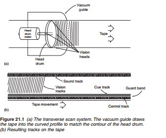
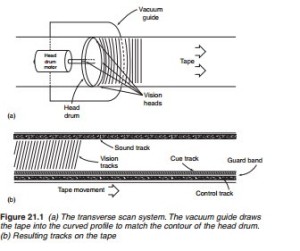
Two more factors were required for success, and these were engineered by Dolby, Ginsburg and Anderson, of Ampex between 1952 and 1955. The problems associated with the tape-track configuration were solved by the use of a horizontal head drum, containing four heads and rotating on a shaft mounted parallel to the direction of tape motion as shown in Figure 21.1a. The video heads lay down parallel tracks across the tape width, slightly slanted (see Figure 21.1b) with each head writing about 16 televi- sion lines per pass. The tape-to-head speed (i.e. the writing speed) at an incredible—to us today—40 m/s was most adequate, with response beyond 15 MHz. The final hurdle was cleared with the introduction of an FM recording system; this involves frequency modulating a constant- amplitude carrier with the picture signal before application to the record- ing head. The Ampex Quadruplex system was enthusiastically taken up by TV broadcasters, and rapidly became a world standard. For less exacting requirements and limited funds, a simpler recording system was really needed, and this gave birth to the helical scan system. The idea of a rotat- ing video-head drum containing one or two heads, each laying down one complete television field per pass, was first mooted in 1953. The Japanese Toshiba company was foremost in the field in the early days, though several
other companies were working on the idea. By 1961, a handful of manufacturers were demonstrating helical machines, all with the open-reel system, each totally incompatible with all the others, and none having a perform- ance which could approach that of the quadruplex system. The market for these machines was intended to be in the industrial and educational spheres, with very little regard as yet to the domestic market.
By 1980, the pace of machine development quickened with VHS ruled supreme in the UK and a wide range of software appeared alongside. In 1980, piano keys had given way to light-touch sensors and remote control, sophisticated timers and programmers had appeared and a form of freeze frame had been introduced. Another significant event of 1980 was the appearance of a new helical VCR format, the Philips/Grundig Video 2000 system, for use with the video compact cassette (VCC). The compact cassette designation indicated the intention that it should become as popular as the universally used audio compact cassette. In the event, V2000 format was not successful and production had ceased by early 1986. It used an advanced dynamic track following (DTF) tracking system, very similar to that of the later and more successful Video-8 format, whose ATF (automatic track finding) feature will be described later.
Specialised ICs had been making steady inroads into domestic VCR design, large-scale integration (LSI) and microprocessor devices becoming commonplace in contemporary machines. These made possible advanced remote control systems, comprehensive timers and programmers, trick- speed, still-frame and visual search features. They also led a trend away from mechanical complexity in the tape deck and towards electronic con- trol of direct-drive systems; this considerably simplified the mechanics of the tape transport, threading and head drive systems, while retaining a relatively low electronic component count.
Advances had been made, too, in the field of portable VCR equipment. Purpose-designed battery operated machines became available in VHS, VHS-C and Video-8 format for outdoor location work. Those currently on offer incorporate the camera section and video recorder in one unit— camcorders. In this realm, there was strong competition between the VHS camp whose champions are JVC and Panasonic, and the Video-8 protago- nists, led by Sony of Japan and having in its ranks many companies with backgrounds in the world of conventional and cine photography. Details of VHS, VHS-C and Video-8 formats will unfold throughout this chapter and the next, and the relative merits of the formats (including the high-definition [HD] variants, S-VHS and Hi-8) will be discussed later in this chapter.
The mid-nineties saw the advent of the digital format DV, primarily intended for camcorders, and taking advantage of MPEG compression techniques described in Chapter 4. For the first time here was a format backed by virtually all the manufacturers in the ‘domestic’ field, and DV- format products, with compatibility across the board, became available in a wide range of types and prices, with competition working well for the consumer. The late 1990s saw the introduction by Sony of Digital-8 format, a hybrid capable of dual-standard operation with Video-8/Hi-8 and digi- tal recording and playback. JVC began marketing D (data)—VHS in 1999, a ‘homedeck’ format for use with DTV television systems, and disc-based digital camcorders made their first appearance, from Hitachi, at about the same time. We shall look at the operation of digital tape systems later in this chapter. At the turn of the new century computer-type hard disc drives were incorporated into DTV set-top boxes (STBs) for recording (auto-recording) of TV programmes.

