AVC motion compensation
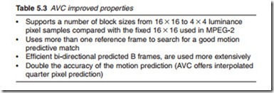
AVC achieves its most significant gains over MPEG-2 through substantial improvements to the motion compensated prediction process. Table 5.3 gives a summary of these improvements.
AVC uses smaller picture areas with vectors that have accuracy down to 1/4 pixel. In interpolating the motion vector, more than one previous picture frame may be used. This provides an advantage in a situation where a non-typical picture such as a flash from a firing gun is inserted in a normal sequence. MPEG-2 which relies on a singles previous reference picture, cannot handle such situations adequately. AVC on the other hand deals with this simply by referring to the picture before the gun flash when calculating the motion vector. Bidirectional inter-frame coding is also enhanced with this capability since it improves the accuracy of the motion vector which can now take account of few earlier pictures as well as one later picture. While in MPEG-2, a B frame could not be used as a reference picture frame, with AVC, this is now possible.
AVC 16 X 16 macroblocks may be coded with one and up to sixteen motion vectors. With MPEG-2 prediction is carried out using a 16 X 16 macroblock which is highly inefficient if the edge of a moving object such as a football goes across the macroblock resulting in a larger residual error. In such cases, better results are obtained if the macroblock is divided into different sizes and shapes according to the angle and position of the edge of the object. The 16 X 16 macroblock may be partitioned into four high level partitions: 16 X 16, 16 X 8, 8 X 16 and 8 X 8. When the 8 X 8 option is selected, it may be further subdivided into three low-level finer partitions: 8 X 4, 4 X 8 and 4 X 4 as illustrated in Figure 5.8.
A separate motion vector is required for each partition or sub-partition. Each motion vector must be coded and transmitted; in addition, the choice of partition(s) must be encoded in the compressed bitstream. Choosing a large partition size (e.g. 16 X 16, 16 X 8, 8 X 16) means that a small number of bits are required to signal the choice of motion vector(s) and the type of partition; however, the motion compensated residual may contain a sig- nificant amount of bits in frame areas with high detail. Choosing a small partition size (e.g. 8 X 4, 4 X 4) may give a lower-energy residual after motion compensation but requires a larger number of bits to signal the motion vectors and choice of partition(s). The choice of partition size therefore has a significant impact on compression efficiency. In general, a large partition size is appropriate for homogeneous areas of the frame and a small partition size may be beneficial for detailed areas. This method of partitioning macroblocks into subpartitions of varying sizes in order to cater to the shape of an edge is known as tree structured motion compensation.
Once the motion vector is obtained from the luminance component, it is then used for the chrominance components. Each chroma block is parti- tioned in the same way as the Y component, except that since the resolution of each chroma component in a macroblock (CR and CB) is half that of the luminance Y component, the chrominance partition sizes are halved. An 8 X 16 partition in Y corresponds to a 4 X 8 partition in chroma and an 8 X 4 partition corresponds to 4 X 2 in chroma; and so on. The horizontal and ver- tical components of each motion vector (one per partition) are therefore halved when applied to the chroma blocks.
Motion vector prediction
Encoding a motion vector for each partition can take a significant number of bits, especially if small partition sizes are chosen. Motion vectors for neighbouring partitions are often highly correlated and so each motion vec- tor may be predicted from vectors of nearby, previously coded partitions. A predicted vector, MVp, is formed based on previously calculated motion vectors. The difference between the current vector and the predicted vector, MVD is then encoded and transmitted. The method of forming the predic- tion MVp depends on the motion compensation partition size and on the availability of nearby vectors. At the decoder, the predicted vector MVp is formed in the same way and added to the decoded vector difference MVD.
New transforms and quantisation
Once the motion vectors have been identified, the next stage is to produce the frame difference or the residual error. In AVC this is done using enhancements of proven MPEG-2 mechanisms. MPEG-2 uses a discrete cosine transform (DCT) based on an 8 X 8 pixel block. This is effective for some applications, but imperfect, since errors in the math would result in loss of data. To get around this weakness, the new AVC technology uses a new pseudo DCT 4 X 4 integer transform that is designed for accuracy, ease of processing and can be implemented using 16-bit integer values with addition and bit-shifting operations. Coding using this transform is fully reversible at the decoding stage of the receiver.
Another area that will yield significant gains relates to the bit-allocation process. Quantisation or bit rate control is the key part of the process, enabling the system to determine how to use bits wisely to attain the desired bit rate. MPEG-2’s DCT is fully defined, with no room for improvement. In contrast, the quantisation rate control process offered by AVC has the potential for continued advancement over time.

