Transfer characteristic and bias
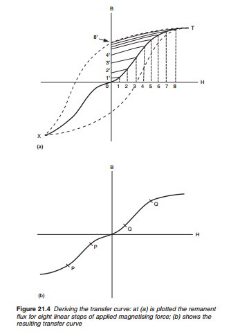
Figure 21.4a is based on the previous diagram, but shows the initial mag- netising curve in solid line (T0X) with the hysteresis curve in dotted out- line. If we apply a magnetising force, 1H, and then remove it, the remnant flux falls to a value ‘1’. A larger magnetising force 3H will, if applied and removed, leave a remnant force ‘3’, and so on, up to saturation point 8H and remanence point ‘8’. The same applies in the negative direction, and
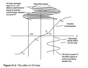
plotting remanence points against applied force we get the curve shown in Figure 21.4b. This is the transfer characteristic. It is very non-linear at the middle and ends, but for a typical recording type, will contain reason- ably linear sections on each flank, PP and QQ. If we can bias the recording head to operate on these linear parts of the transfer characteristic, the reproduced signal will be a good facsimile of that originally recorded. The d.c. bias (Figure 21.5) puts the head into one of the linear sections, but the recorded signal will be noisy and inadequate; a.c. bias, shown at the top of Figure 21.5, allows the head to operate in two quadrants, with supe- rior results. We shall see that the chrominance signal in a VCR is recorded along with a bias signal, which is in fact the FM carrier for the luminance signal.


