CHROMINANCE PLAYBACK
An outline of the chroma replay system for VHS is given in Fig. 14.8. The chroma input from the replay heads is based on 626.952 kHz and selected by a low-pass filter. It contains crosstalk as well as frequency and phase errors. Three processes must be carried out on
it: up-conversion, crosstalk cancellation and de-jittering. These individual functions are somewhat mixed in the diagram. Up-conversion takes place in balanced modulator 2 whose second input is a locally generated 5.060571 MHz wave. The frequency difference between these two inputs is 4.433619 MHz, as required for a standard CVBS signal, and this is selected by an output filter. As during record, it is this second input to balanced modulator 2 which steers the output colour signal in special ways to overcome the bad influences of crosstalk and timing jitter. As during record, too, the local signal is produced in balanced modulator 1, whose inputs are crystal oscillator VX01 wave at 4.435571 MHz; and the 625 kHz (40 times line frequency) carrier derived from the same phase-locked- loop as before. The phase selection system works in identical fashion too: 625 kHz carrier for all head A sweeps are at zero phase, whereas those for head B sweeps step 90° forwards on each TV line.
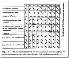
The phase advance thus imparted to the heterodyne signal for head B’s up-conversion process will, because both mixers are now operating in subtractive mode (difference beat output used in both cases), have the effect of advancing the phase of the up-converted head B colour signal. The original phase retard characteristic is thus cancelled out in the up-conversion process. Phase normality, then, is restored to the chroma output signal in which the burst (and hence chroma-signal) phases are now as transmitted – shown by the large arrows in the third and fourth rows of Fig. 14.7.
Timing correction
The timing jitter imparted to the chrominance signal during record and playback must now be eliminated. It can only be done by add- ing an equal jitter factor to the ‘local’ input to balanced modulator 2, such that even though the off-tape signal is varying in terms of frequency and phase, the difference between them is always precisely 4.433619 MHz.
The 625 kHz input to balanced modulator 1 is locked to off-tape line sync pulses by virtue of the 2.5 MHz PLL. All jitter influences (during record and playback) on the chroma signal are also applicable to the line sync pulse component of the composite luminance signal which accompanies it both on and off the tape; colour frequency errors are cancelled out, then, by the influence of the jitter signal present in the 625 kHz (and hence 5.06 MHz) heterodyne signals.
Frequency correction by itself is not adequate to fully stabilise the replay chroma signal, however. Very short-term variations in timing of off-tape subcarrier upsets its phase in a random way between ‘PLL updates’ once per line. A second loop is therefore provided to cater for phase correction of replayed subcarrier. It is based on the second input to balanced modulator 1, and depends on ‘steering’ the phase of VXO1 to inject a second jitter-cancelling correction signal into the balanced modulators.
A sample of replayed colour burst is gated out of the up-converted chroma output and compared in a phase detector with a reference c.w. wave from a stable crystal oscillator. The error output from the phase detector is a direct indicator of the phase jitter in the replayed subcarrier, and is applied to VXO1 in the correct sense to cancel that jitter. This second PLL locks up the videorecorder’s chroma output to the internal 4.433619 MHz reference crystal, which itself now ‘masters’ the subcarrier reference oscillator in the TV or monitor being fed. If the second PLL should come out of lock a playback colour killer shuts down the chrominance channel to prevent spuri- ous colour patterns appearing on the screen.
A second phase detector is present in Fig. 14.8. Its function is not only to provide the above-described colour-killer action, but to monitor the degree of correction being provided via phase director 1. Whenever a large correction is required, it is reduced by the action of phase detector 2 which acts to invert the 625 kHz local signal either via the phase select section or by a separate inverting switch. The effect is that of a 180° phase change, and the operating range of phase detector 2 is thus reduced.
In addition to these artifices, some home video equipment incorporates timebase correction, in which jitter is ironed out by an electronic (digital) data store. The unstable signal is A-D converted and loaded into a memory chip, then read out almost instantaneously according to a new and stable set of sync pulses.

