Polarity inversion
In LC cells, it is the magnitude of the applied voltage which determines the amount of light transmission. Such voltage may be d.c. or a.c. Applying a voltage of the same (d.c.) polarity to an LC cell would cause electroplating of one electrode resulting in what is known as ‘d.c. stress’ causing deterioration in image quality. To prevent polarisation (and rapid permanent damage) of the LC material, the polarity of the cell voltage is reversed, a process known as polarity inversion. Polarity inversion may be implemented in three different ways: frame inversion, line (or horizontal) inversion and dot inversion (Figure 11.14). It will be noticed that line inversion incorporates frame inversion as well since a positive line in one frame becomes negative in the following frame and vice versa.
Unfortunately, it is very difficult to get exactly the same voltage on the cell in both polarities, so the pixel-cell brightness will tend to flicker. This flicker is most noticeable with frame inversion in which the polar- ity of the whole screen is inverted once every frame resulting in a 25-Hz and 30-Hz flicker for PAL and NTSC, respectively. Flicker may be reduced by having the polarity of adjacent lines using line inversion thus cancelling out the flicker. Better results may be obtained with dot inversion. In this way, the flicker can be made imperceptible for most ‘natural’ images.
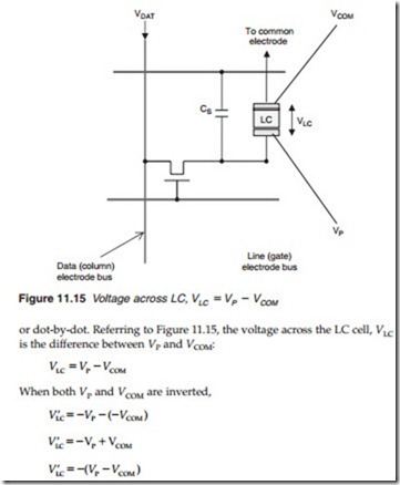
Polarity inversion is carried out by inverting both the pixel cell electrode
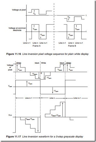
The line inversion sequence for three lines of a plain white screen is shown in Figure 11.16. For line n, the pixel voltage VP for all the pixels on the line is high to remove the 90º twist of the LC and remains constant throughout ‘line n’ since all pixels are at the same luminance level. They are then inverted for the following ‘line n + 1’ and so on. The pixel voltage VCOM is also constant over one whole line and inverted for the following line. For a 5-step greyscale display, the pixel values change along the line as shown in Figure 11.17 starting with Vwhite for peak white and –Vblack for black at the end of the line. This is then inverted and repeated for the next line and so on. VCOM, on the other hand, is constant over one line and inverted over the next. The LC voltage VLC, being the difference between
VP and VCOM is that shown in Figure 11.17 inverted every line. For dot inversion, the pixel voltage and the common electrode voltage will invert on successive dots.


