Modulation system
To be able to record a video signal embracing 18 octaves or more, it is necessary to modulate the signal onto a carrier and ensure that the octave range of the carrier is within the capabilities of the tape recording system. While the carrier could be amplitude modulation (AM), the frequency modulation (FM) system has been adopted because it confers other advantages, particularly in the realm of noise performance. An FM signal can be recorded at constant level regardless of the modulating signal amplitude, so that head losses and effects of imperfect head-to-tape contact are less troublesome. To achieve a picture replay with no perceptible background noise (snow), the S/N ratio needs to be over 40 dB, and this can be achieved by an FM recording system in a domestic VCR. Professional and broadcast machines can do much better than this!
An FM system, familiar to us in VHF sound broadcasts, starts with a continuous wave (CW) oscillator to generate the basic carrier frequency. The frequency of the oscillator is made to vary in sympathy with the modulat- ing signal, audio for VHF sound transmitters, video for VCR recording systems and satellite broadcasts. For any FM system, the deviation (the distance that the carrier frequency can be ‘pulled’ by the modulating sig- nal) is specified. In VHF sound broadcasting, it is ±75 kHz, giving a total frequency swing of the carrier of 150 kHz. In a VCR, carrier frequencies are specified for zero video signal amplitude—represented by the bottom of the sync pulse—and full video signal amplitude, i.e. peak white.
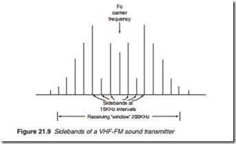
An FM system theoretically generates an infinite number of sidebands, each becoming less significant with increasing distance from the carrier frequency. Figure 21.9 shows the sidebands of a VHF-FM sound broadcast transmission. The modulating frequency is 15 kHz, and the sideband dis- tribution is such that the first eight sidebands on either side of the carrier are significant in conveying the modulation information. Thus to ade- quately receive this double-sideband transmission, we need a receiving bandwidth of 240 kHz or so—in practice 200 kHz is sufficient, and this is the allocated channel width.
A bandwidth of 200 kHz for the transmission of a 15-kHz note seems very wasteful of spectrum space and certainly will not do for our tape sys- tem in which elbow-room is very limited! However, by making the carrier deviation small compared with the carrier frequency, the situation may
greatly be improved. This ration is known as the modulation index which is given by the formula
For the above example, the modulation index = 75/15 = 5.
If we can reduce the modulation index, the significant sidebands draw closer to the carrier frequency, and at modulation indexes below 0.5, the energy in the first sideband above and below the carrier becomes great enough for them to convey all the necessary information in the same way as those of an AM signal. In video tape recording we go a step further and use only one sideband along with a part of the other, similar to the vestigial sideband scheme used with analogue television broadcast.
By using a low modulation index, then, the sidebands of the FM signal can be accommodated on the tape. FM deviation has to be closely controlled and carrier frequencies carefully chosen to avoid trouble with the sidebands, which if they extend downwards from the carrier to a point beyond zero frequency, will not disappear, but ‘fold back’ into the usable spectrum to interfere with their legitimate fellows, leading to beat effects and resultant picture interference. The effect of a folded sideband is shown in Figure 21.10.
