Magnetic tape basics
All magnetic materials, video tape coatings amongst them, may be regarded for practical purposes as consisting of an infinite number of tiny bar magnets, each with its own north and south poles. This is a simplification, but suits our purposes well. In the natural state, these bar magnets are randomly aligned within the material so that their fields cancel one another out, and no external magnetic force is present. To magnetise the material, be it a blank tape or a solenoid core, we have to apply an exter- nal magnetic force to align the internal magnets so that they sit parallel to one another, with all their N poles pointing in the same direction. When
the external field is removed, most of the magnets remain in alignment and the material now exhibits magnetic properties of its own.
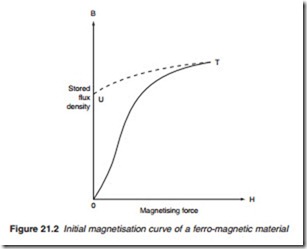
The relationship or transfer curve (Figure 21.2) between the external force and the retained magnetism on the tape is not linear. The transfer curve is a graph with the magnetising force (H) plotted along the horizontal axis, and the stored flux density (B) on the vertical axis. Our starting point is in the centre, point 0. Here, no external magnetising force is present, and the magnetic material’s internal magnets are lying in random fashion— hence zero stored flux. Let’s suppose we now apply a linearly increasing external flux. The flux density (strength of magnetism) in the material would increase in a non-linear fashion as shown by the curve 0–T. At point T, the material has reached magnetic saturation and all its internal mag- nets are rigidly aligned with each other—no increase in applied magnetic force will have any effect. If we now remove the magnetising force, bring- ing the H coordinate back to zero, we see that a lot of magnetism is retained by the specimen, represented by point U. This is the remanence of the material, the ‘stored charge’ as it were. For recording tape, it needs to be as high as possible.
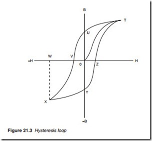
Figure 21.3 is an expansion of Figure 21.2 to take in all four quadrants. We left the material at point U with a stored flux. To remove the flux and demagnetise the tape material, it is necessary to apply a negative mag- netising force, represented by 0–V, whereupon stored flux B returns to zero. Further negative applied force (V–W) pushes the stored flux to satu- ration point in the opposite direction, so that all the magnets in the tape
are once again aligned, but all pointing the other way, represented by point X. Removal of the applied force takes us back to the remanence point, this time in the negative direction – point Y. To demagnetise the tape, a positive applied force 0–Z is required, an increase of which will again reverse the stored flux to reach saturation once more at point T. The diagram is called a magnetising hysteresis curve and one cycle of an applied magnetising waveform takes us right round it. It can now be seen how the ‘degaussing’ or erasing process works. Here, we apply a large alternating magnetic field sufficient to drive the material to saturation in both direc- tions. The field is then allowed to decay linearly to zero, creating smaller and smaller hysteresis loops until they disappear into a dot at point 0, and the material is fully demagnetised.

