Pre-emphasis
Noise is the enemy of all recording and communications systems, and in FM practice it is common to boost the HF components of the modulating signal prior to the modulation process, a process known as pre-emphasis,
and so do we in VCR FM modulation circuits. The effect of this after demodulation (in the post-detector circuit of a radio or the playback amplifier of a VCR) is to give a degree of HF lift to the baseband signal. In removing this with a filter, gain is effectively reduced at the HF end of the spectrum, with an accompanying useful reduction in noise level. The idea is shown in Figure 21.11, which illustrates the filter characteristics in record and replay, along with the effect on the noise level.
Principle of helical scan
We have seen that the necessary high head-scanning speed was first achieved by fast longitudinal recording techniques, then in the successful Quadruplex system by transverse scanning of the tape by a four-head drum with the video heads mounted at 90° intervals around its periphery. The transverse scan method has a lot going for it! The very high writing speed confers great bandwidth, enabling full broadcast-specification pictures to be recorded and replayed. The relatively wide tracks are almost at right angles to the tape direction so that any jitter or flutter in the tape transport has little effect on the timing of the video signal, merely causing slight momentary tracking inaccuracies, easily catered for by the wide track and the FM modulation system in use.
The cost of transverse scanning machines is high because of the need for a complex head drum system and precision vacuum tape guides. To maintain the necessary intimate contact between video head and tape, all VCRs have their head tips protruding from the surface of the drum so that they penetrate the tape and create a local spot of ‘stretch’. Hence, the need
for a precise vacuum guide at the writing/reading point in a trans- verse machine to maintain correct tape tension. These techniques are not amenable to domestic conditions or budgets, and the alternative and simpler helical system has undergone much development. It is now used exclusively.
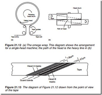
In a helical scan system, several problems are solved in one go, but other shortcomings are introduced. The idea is to wrap the tape around a spinning head drum with entry and exit guides arranged so that the tape path around the head takes a form of a whole or part-helix. The principle is shown in Figure 21.12 where a video head in the course of one revolu- tion enters the tape on its lower edge, lays down a video track at a slant angle and leaves the upper edge of the tape ready to start again at the tape’s lower edge on the next revolution. During the writing of this one track, the transport mechanism will have pulled the tape through the machine by one ‘slant’ video-track width, so that track 2 is laid alongside the first; each track is the width of the video head. Figure 21.13 shows how this works and gives an elementary impression of the track formation.
436 Newnes Guide to Television and Video Technology
Let’s look at the strengths and weaknesses of the helical format. Tape tension and hence head-tip penetration is now governed by the tape trans- port system rather than a precision guide arrangement. One or two com- plete television fields can be laid down per revolution of the head drum, so that the problem of matching and equalising heads (to prevent picture segmentation) disappears. In a single-head machine such as we have described, no head switching during the active picture period is necessary. Two-head helical machines have a simple head-switch or none at all; what price do we pay for these advantages? The main penalty is timing jitter in the recorded and replayed video signals. Because the tracks are laid at a small angle to the tape direction (about 5° off horizontal for VHS) they may be regarded as virtually longitudinal, so that the effects of the inevitable transport flutter, variations in tape tension, bearing rumble, etc. will be to introduce minute timing fluctuations into the replayed signal. This effect cannot be eliminated in any machine, and causes problems with colour recording and certain types of TV receiver.
In practice, two video heads are used in the drum of a helical VCR, pic- tured amongst others in the photo of Figure 21.14. The two-head system means that the tape needs only to be wrapped around half the video head drum perimeter, with one head joining the tape and beginning its scan as the other leaves the tape after completing its stint. To give a degree of overlap between the duty cycles of the two heads, the tape wrap is in fact
about 186°, slightly more than half a turn. This is known as an omega (m) wrap outlined in Figure 21.15.


