The photodiode detector assembly
The photodiode assembly consists of a number of photodiodes which detect the strength of the reflected laser beam and produce a number of signals including the RF, focus error, FE and tracking error (TE) signals. The RF signal contains the actual video, audio and other information. Since the pits and lands reflect the beam with different strengths, the output level from the photodiodes will thus represent the pits and lands, i.e. a bitstream of zeros and ones.
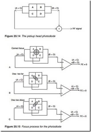
The detector that monitors the main beam is divided into four quad- rants or segments, A, B, C and D as shown Figure 20.14. The sum of the outputs of the four segments (A + B + C + D) represents the RF signal strength which is used for data processing. The same four-quadrant pho- todiode is used to produce the focus error (FE) signal.
Focus error
When the beam is correctly focused, the reflected beam forms a circular pattern on the photodiode (Figure 20.15a). However, if the beam is off focus, the beam forms an elliptical shape with a different aspect ratio as
shown. By comparing (A + C) with (B + D) a FE signal is produced (Figure 20.16b and c). When the beam is in focus (A + C) – (B + D) = 0. Otherwise, FE would be positive when the focus is too short and negative when the focus is too long.
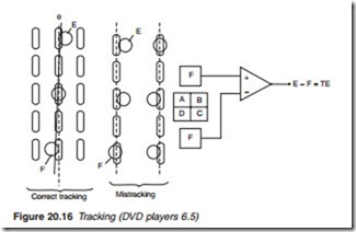
Apart from the main beam which is used for the RF and FE signals, there are two side beams produced by the grating lens. These two side beams are directed to two separate photo-detectors (E and F) placed on each side of the main beam photodiode assembly as shown in Figure 20.16.
When the beam is on track, the outputs of diodes E and F are equal. However, if the beam leaves the track, it will energise one of the diodes more than the other producing a positive or negative tracking error. Other alternative techniques may also be used by different manufacturers, all of which involves the use of additional photo-diodes assemblies.

