COMPRESSOR PERFORMANCE
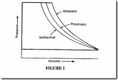
Practical compressors normally work on a polytropic process, ie intermediate between true isothermal and true isentropic- Figure 1. Isothermal remains the ideal, and much effort is made by compressor designers to get close to it. A few percentage points reduction in input power can make a significant difference to the economies of air compression.
Multi-stage compression with intercooling between stages is a widely used technique.
Theoretically the most efficient design of a multi-stage compressor has the same pressure ratio for each stage. Multi-stage compression increases the volumetric efficiency and reduces the power consumption, the power input being a minimum if the total work is divided equally between the stages. When estimating the total power consumption and in evaluating the overall efficiency the power used in running the intercooling process has to be taken into account. The curves of Figure 2 demonstrate the argument. The first stage polytropic is close to the isentropic curve, but at the cone!usion of this stage airtemperature is reduced to its original value by intercooling and the volume is reduced. The second stage polytropic curve originates at the isothermal line and follows its own isentropic line. The shaded area represents the saving by intercooling. The desirability of multistage operation is greater with increasing final pressure and required capacity.
Oil or water flooding in a single-stage rotary compressor is another attempt to reduce the value of the polytropic exponent.
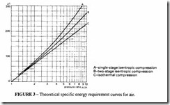
In order to compare the various compression cycles, it is useful to calculate the power required for the various cycles mentioned above and with a two stage compressor. For a pressure ratio of 8:1 the theoretical power per 1/s of air compressed is 0.208 kW for isothermal, 0.284 kW for isentropic, 0.248 kW for polytropic (n = 1.2) and 0.242 kW for a 2-stage compressor. See Figure 3.
Multi-staging is valuable for other reasons than efficiency. It is usually necessary to limit the temperature to which the components of the compressor are subject and intercooling achieves that. A large pressure difference in a single stage can reduce the volumetric efficiency through excessive internal leakage. Mechanical complications impose a practical limit to the number of stages that are possible in a given application: mobile compressors, built for cheapness and to have a limited life are more likely to have a small number of stages than a fixed installation, built for economy in operation and a long life. Mobile oil-flooded screw compressors commonly have a pressure ratio of 8:I and often as high as 13:I, whereas a comparable stationary unit would have two or three stages.
In estimating the performance of compressors, it is essential to distinguish between the various types of efficiency, and the sources of power loss. From the designer’s point of view the internal isentropic efficiency is important in estimating the thermodynamic efficiency of the design. A practical compressor is burdened with more than the thermo dynamic losses. Further possible sources of losses are:
• Leakage past the piston or compression element.
• Heating of the inlet air, resulting in a reduced density and consequent reduction in capacity.
• Flow losses in the delivery passages due to restrictions in the delivery ports.
• Flow losses in the intake caused by the need for inlet valves, intake filters and restrictions in the inlet passages. Frequently manufacturers will quote performance values for the “bare air end”, leaving out intake and delivery losses.
• Mechanical drive losses introduced by the gearing or by other drive mechanisms.
• Power absorbed by the cooling fan and by the lubrication pump.
Reciprocating compressors
As explained in the chapter on Compressor Classification and Selection, reciprocating compressors can adopt a variety of different configurations and can be single- or multi stage. The same method of performance estimation applies to them all.
The capacity can be readily calculated from the product of the total swept volume and the volumetric efficiency.
The next factor to be determined is the value of the index of compression, the polytropic exponent. In multistage compressors employing interstage cooling, the overall compression cycle approaches isothermal, but each individual stage is closer to isentropic, so it is convenient to analyse each stage separately. For modern high and medium speed compressors, the polytropic index can be taken as equal to the isentropic index (ie n = 1.4);
for low speed compressors a value of n = 1.3 is often used. The stage pressure ratio is determined by the pressure set by the delivery valves.
The inlet pressure and temperature of the inlet to the next stage depends on the degree of interstage cooling. In practice perfect cooling down to the inlet temperature is not possible. The cooling system necessarily absorbs power either in driving a fan or circulating the cooling water and this must be taken into account in determining the overall power required. Ten to 15% of the input power should be allowed for cooling purposes.
Volumetric efficiency
One characteristic of a reciprocating compressor is the clearance volume that remains in the cylinder at top dead centre after the delivery stage is complete. This is usually expressed as a proportion of the swept volume and typically has a value of 0.06 to 0.12. This volume is not discharged but expands until it occupies the cylinder volume. The effect of this is to modify the shape of the indicator diagram as in Figure 4. Theoretically this expansion represents no loss of energy if the index of expansion equals the index of compression (bearing in mind that the compression is isentropic and reversible, so the energy used is reclaimed).
The volumetric efficiency of the compressor is a function of the first stage geometry, although for design purposes the separate stages can be separately analysed. It is given by
p 1 and P2 are the intake and delivery pressures in the first stage.
K is a factor depending on valve losses, intake air heating, leakage and pressure ratio. K can be taken as 0.96 for an initial estimate.
Vc is the relative clearance volume.
zl is the compressibility factor at intake.
‘k.is the compressibility factor at discharge.
m is the index of expansion, which as a first approximation is equal to y, the isentropic index.
The expansion index varies with pressure according to the following: For the first stage m = 1.20 For the fourth stage m = 1.35
For the second stage m = 1.25 For subsequent stages m = ‘( For the third stage m = 1.30
A high volumetric efficiency is not necessarily better than a lower one; its significance lies in the calculation of the compressor capacity. If,however, the low efficiency is caused by leakage, then the design is at fault.
Other positive displacement types (screw and vane)
One general feature of these types is that they rely on the position of the delivery port to determine the built-in pressure ratio. (It would be more correct to refer to a built-in volume
ratio, but the fonner is more common.) The position of the port is usually calculated on an assumed isentropic compression.
Operation at other than the design pressure, as for example when the pressure control valve in the delivery is set incorrectly, would result in the modified diagram of Figure 5 and wasted power.
Performance of screw compressors
The displacement of a screw compressor is calculated from
Note that there is no clearance volume as in reciprocating unit. Figure 6 shows a typical set of volumetric efficiency curves for a modern screw.
The theoretical power can be found, as in the case of a reciprocating compressor, from
 It might be thought that the injection of massive quantities of oil into the compression chamber (typically, the ratio of the mass flow of the oil to that of the air is of the order 10:I) would result in an isentropic index close to unity. In fact, the flow velocity is so great that the actual heat transfer between air and oil takes place in the relatively static conditions in the oil reclaimer rather than in the compression chamber. The calculations on power can best be done by assuming isentropic compression and modifying the index from practical tests. The isentropic efficiency depends on the particular screw design. Typical curves are given in Figure 7.
Performance of vane compressors
The swept volume of these units is readily calculated from the crescent area between the vanes.
The same remarks about isentropic efficiency apply as for screw compressors. When these units are oil flooded, oil churning represents one of the main power losses. There is little leakage across the outer edge of the vanes, because centrifugal force keeps them in intimate contact with the cylinder. There is, however, leakage across the ends of the vanes, which are not well sealed by the oil.
Performance of Roots and similar types
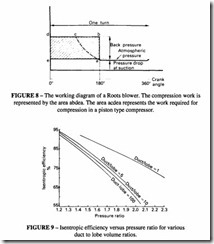
There is no built-in pressure ratio in these units and their efficiency is low, see Figure 8. Some improvement in efficiency is possible by adjusting the ratio of the volume in the
delivery duct (ie the volume between the outlet port and the delivery valve) to the volume of the compressor lobes. See Figure 9.
Dynamic compressors
Any turbo machine operated at constant speed is capable of delivering a wide range of volumes with only a small variation in pressure. If the volume is decreased by throttling on the discharge side, pressure will also decrease. Pressure developed when the discharge is completely throttled will depend on the machine design and operating speed, but will be always lower than the maximum pressure. It is thus a characteristic of aerodynamic machines that dangerously high pressures cannot be built up under any operating conditions and so relief valves are not necessary in the discharge line. Regulation can be achieved either by throttling on the discharge side or variation in the impeller speed (or both).
The use of a valve offers the simplest form of control over pressure or capacity but throttling always represents an unrecoverable power loss. Speed variation is, therefore, a more economic form of control when the compressor characteristics can be expressed in the form of a series of curves which may be superimposed on the demand curve to establish the required operating point, as in Figure I0. In other words, by adjusting the speed, the compressor characteristics may be matched to any required values of pressure and capacity within the operating limits of the compressor and its driver. Efficiency will not necessarily be a maximum, unless this operating point corresponds to the design value for maximum efficiency.
The variable speed, capacity and adiabatic head can be related in terms of specific speed:
This is a relative value only and has little significance other than as a design specific speed or value at which a given type of casing shows its maximum efficiency. It then serves as an index of classification for the form of the impeller in that type of casing. The compressor may be operated over a range of speeds, capacities and adiabatic heads, and thus a wide range of specific speeds. These actual or operating speeds are useful only as a basis for comparing performance relative to the performance obtained at the design specific speed.
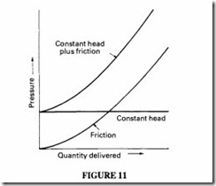
The demand load itself will depend on the operating conditions and may involve working against a constant head or pressure, against frictional resistance, or a combination of both. In the former case the demand load will be constant and in the other two cases will vary with capacity- Figure II.The resultant demand curve may also vary under actual working conditions due to a change in head or frictional resistance. The working point of
Constant head plus friction
the compressor can be changed, eg by means of a butterfly valve installed preferably near the compressor inlet or near the discharge. Other methods of adjusting the compressor characteristics, and hence the pressure and capacity, include the use of adjustable diffuser vanes and adjustable inlet guide vanes.
Estimation of compressor performance with altitude
A number of factors combine to modify the performance of a compressor at altitude. Performance tests should always be used as the primary source of information. Where the results of such tests are not available, an estimate based on theoretical considerations can be made.
Referto Table 6 in the chapter on Properties of Air and Gases, for details of the standard atmosphere. Note that the density, temperature and pressure all fall with increasing altitude. If the compressor is designed to produce a given amount of air at a given pressure at sea level its performance at altitude will be affected, not only because of the change in inlet conditions but also because it will no longer be able to operate at its optimum design efficiency.
There are two ways of looking at the change with altitude: when operating the same compressor at the same speed and same delivery pressure, the power to run it will be Jess at altitude; when it is desired to obtain the same useful output, the power required will be greater. The actual energy content of the compressed air is measured by the mass flow rather than the volume flow at inlet conditions, so a calculation of the extra power required at altitude can be made from an alternative form of the power equation:
As an example one can use this equation to compare the power at altitude with the power at sea level, when delivering air at a constant mass flow and a constant delivery pressure
A further fall in performance will come from the change in volumetric efficiency, caused either by the clearance volume effect in a reciprocating compressor or from the change in the built-in pressure ratio in a rotary unit.
Table 2 gives some estimates of the observed reduction in the power and capacity in a variety of different compressor designs.
These considerations take no account of the reduction in power from the prime mover. Both electric motors and internal combustion engines give reduced output at altitude. Electric motors have a reduced performance of about 5% for every I 000 m increase in altitude through poorer cooling. For internal combustion engines, reliance has to be placed on the manufacturers’ tests. Turbo-charged engines are better in this respect than naturally aspirated ones.


