Seals
Leakage from a hydraulic or pneumatic system can be a major problem, leading to loss of efficiency, increased power usage, temperature rise, environmental damage and safety hazards.
Minor internal leakage (round the piston in a double-acting cylinder, for example) can be of little consequence and may even be deliberately introduced to provide lubrication of the moving parts.
External leakage, on the other hand, is always serious. In pneumatic systems, external leakage is noisy; with hydraulic systems, external loss of oil is expensive as lost oil has to be replaced, and the resulting pools of oil are dangerous and unsightly.
Mechanical components (such as pistons and cylinders) cannot be manufactured to sufficiently tight tolerances to prevent leakage (and even if they could, the resultant friction would be unacceptably high). Seals are therefore used to prevent leakage (or allow a con trolled leakage). To a large extent, the art of designing an actuator is really the art of choosing the right seals.
The simplest seals are ‘static seals’ (Figure 5.17) used to seal between stationary parts. These are generally installed once and for gotten. A common example is the gasket shown in a typical application in Figure 5.17a. The 0 ring of Figure 5.17b is probably the most used static seal, and comprises a moulded synthetic ring with a round cross section when unloaded. 0 rings can be specified in terms of inside diameter (ID) for fitting onto shafts, or outside diameter (OD) for fitting into bores.
When installed, an 0 ring is compressed in one direction.
Application of pressure causes the ring to be compressed at right angles, to give a positive seal against two annular surfaces and one flat surface. 0 rings give effective sealing at very high pressures.
0 rings are primarily used as static seals because any movement will cause the seal to rotate allowing leakage to occur.
Where a seal has to be provided between moving surfaces, a dynamic seal is required. A typical example is the end or cup seal shown, earlier, in Figure 5.9a. Pressure in the cylinder holds the lip of the seal against the barrel to give zero leakage (called a ‘positive seal’). Effectiveness of the seal increases with pressure, and leakage tends to be more of a problem at low pressures.
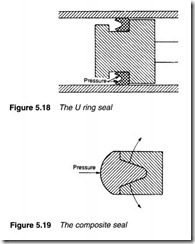
The U ring seal of Figure 5.18 works on the same principle as the cup seal. Fluid pressure forces the two lips apart to give a positive seal. Again, effectiveness of the seal is better at high pressure. Another variation on the technique is the composite seal of Figure 5.19. This is similar in construction to the U ring seal, but the space between the lips is filled by a separate ring. Application of pressure again forces the lips apart to give a positive seal.
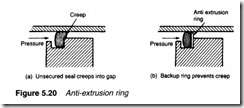
At high pressures there is a tendency for a dynamic seal to creep into the radial gap, as shown in Figure 5.20a leading to trapping of the seal and rapid wear. This can be avoided by the inclusion of an anti-extrusion ring behind the seal, as in Figure 5.20b.
Seals are manufactured from a variety of materials, the choice being determined by the fluid, its operating pressure and the likely temperature range. The earliest material was leather and, to a lesser extent, cork but these have been largely superseded by plastic and synthetic rubber materials. Natural rubber cannot be used in hydraulic systems as it tends to swell and perish in the presence of oil.
The earliest synthetic seal material was neoprene, but this has a limited temperature range (below 65°C). The most common present-day material is nitrile (buna-N) which has a wider temperature range (-50°C to 100°C) and is currently the cheapest seal
material. Silicon has the highest temperature range (-1oooc to +250°C) but is expensive and tends to tear.
In pneumatic systems viton (-20°C to 190°C) and teflon (-80°C to +200°C) are the most common materials. These are more rigid and are often used as wiper or scraper seals on cylinders.
Synthetic seals cannot be used in applications where a piston passes over a port orifice which nicks the seal edges. Here metallic ring seals must be used, often with the rings sitting on 0 rings, as illustrated in Figure 5.21.
Seals are delicate and must be installed with care. Dirt on shafts or barrels can easily nick a seal as it is slid into place. Such damage may not be visible to the eye but can cause serious leaks. Sharp edges can cause similar damage so it is usual for shaft ends and groove edges to be chamfered.
Rotary actuators
Rotary actuators are the hydraulic or pneumatic equivalents of electric motors. For a given torque, or power, a rotary actuator is more compact than an equivalent motor, cannot be damaged by an indefinite stall and can safely be used in an explosive atmosphere. For variable speed applications, the complexity and maintenance requirements of a rotary actuator are similar to a thyristor-con trolled DC drive, but for fixed speed applications, the AC induction motor (which can, for practical purposes, be fitted and forgotten) is simpler to install and maintain.
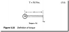
A rotary actuator (or, for that matter, an electric motor) can be defined in terms of the torque it produces and its running speed, usually given in revs per minute (rpm). Definition of torque is illus trated in Figure 5.22, where a rotary motion is produced against a force of F newtons acting at a radial distance d metres from a shaft centre. The device is then producing a torque T given by the expression:
In Imperial units, F is given in pounds force, and d in inches or feet to give T in lbf ins or lbf ft. It follows that 1 Nm = 8.85 lbf ins.
The torque of a rotary actuator can be specified in three ways. Starting torque is the torque available to move a load from rest. Stall torque must be applied by the load to bring a running actuator to rest, and running torque is the torque available at any given speed. Running torque falls with increasing speed, typical examples being shown on Figure 5.23. Obviously, torque is dependent on the applied pressure; increasing the pressure results in increased torque, as shown.
where T is in lbsf ins.
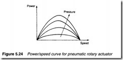
Figure 5.23 illustrates how running torque falls with increasing speed, so the relationship between power and speed has the form of Figure 5.24, with maximum power at some (defined) speed. Power like the torque, is dependent on applied pressure.
The torque produced by a rotary actuator is directly related to fluid pressure; increasing pressure increases maximum available torque. Actuators are often specified by their torque rating, which is defined as:
In Imperial units a pressure of 100 psi is used, and torque is gener ally given in lbf ins.
The allowable pressure for an actuator is defined in terms of pressure rating (maximum applicable pressure without risk of per manent damage), and pressure range (the maximum and minimum pressures between which actuator performance is defined).
Fluid passes through an actuator as it rotates. For hydraulic actuators, displacement is defined as the volume of fluid used for one motor rotation. For a given design of motor, available torque is directly proportional to displacement. For pneumatic actuators, the air usage per revolution at a specified pressure is generally given in terms of STP (see Chapter 3).
Rotational speed is given by the expression:
With the torque rate and displacement fixed for a chosen motor, the user can control maximum available torque and speed by adjusting, respectively, pressure setting and flow rate of fluid to the actuator.
Constructional details
In electrical systems, there are many similarities between electrical generators and electric motors. A DC generator, for example, can be run as a motor. Similarly, a DC motor can be used as a generator. Similar relationships exist between hydraulic pumps and motors and between pneumatic compressors and motors. This similarity is extended as manufacturers use common parts in pumps, compressors and motors to simplify users’ spares holdings.
The similarity between pumps, compressors and motors extends to graphic symbols. The schematic symbols of Figure 5.25 are used to show hydraulic and pneumatic motors. Internal leakage always occurs in a hydraulic motor, and a drain line, shown dotted, is used to return the leakage fluid to the tank. If this leakage return is inhibited the motor may pressure lock and cease to rotate or even suffer damage.
There are three basic designs of rotary or pump compressor; the gear pump, the vane pump and various designs of piston pump or compressor described earlier in Chapter 2. These can also be used as the basis of rotary actuators. The principles of hydraulic and pneumatic devices are very similar, but the much higher hydraulic pressures give larger available torques and powers despite lower rotational speeds.
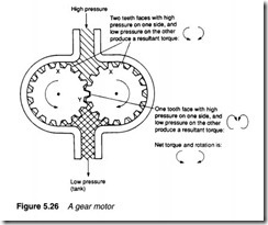
Figure 5.26 shows the construction of a gear motor. Fluid enters at the top and pressurises the top chamber. Pressure is applied to two gear faces at X, and a single gear face at Y. There is, thus, an imbalance of forces on the gears resulting in rotation as shown. Gear motors suffer from leakage which is more pronounced at low speed. They thus tend to be used in medium speed, low torque applications.
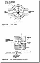
A typical vane motor construction is illustrated in Figure 5.27. It is very similar to the construction of a vane pump. Suffering from less leakage than the gear motor, it is typically used at lower speeds. Like the vane pump, side loading occurs on the shaft of a single vane motor. These forces can be balanced by using a dual design similar to the pump shown in Figure 2.1Ob. In a vane pump, vanes are held out by the rotational speed. In a vane motor, however, rotational speed is probably quite low and the vanes are held out, instead, by fluid pressure. An in-line check valve can be used, as in Figure 5.28, to generate a pressure which is always slightly higher than motor pressure.
Piston motors are generally most efficient and give highest torques, speeds and powers. They can be of radial design similar to the pump of Figures 2.12 and 2.13, or in-line (axial) design similar to those of Figures 2.14 and 2.15. Radial piston motors tend to be most common in pneumatic applications, with in-line piston motors most common in hydraulics. The speed of the piston motor can be varied by adjusting the angle of the swash plate (in a similar manner to which delivery volume of an in-line piston pump can be varied).
Turbine-based motors can also be used in pneumatics where very high speeds (up to 500,000 rpm) but low torques are required. A common application of these devices is the high-speed dentist’s drill.
All the rotary actuators described so far have been pneumatic or hydraulic equivalents of electric motors. However, rotary actuators with a limited travel (say 270°) are often needed to actuate dampers or control large valves. Some examples are illustrated in Figure The actuator in Figure 5.29a is driven by a single vane coupled to the output shaft. In that of Figure 5.29b, a double-acting piston is coupled to the output shaft by a rack and pinion. In both cases the shaft angle can be finely controlled by fluid applied to the ports. These have the graphic symbol shown in Figure 5.29c.

