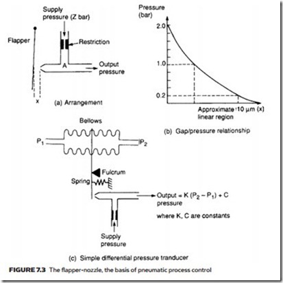
the flapper-nozzle
Most properties (e.g. flow, pressure, level, error, desired valve position) can be converted to a small movement. The heart of all pneumatic process control de- vices is a device to convert a small displacement into a pressure change, which
represents the property causing the displacement. This is invariably based on the flapper-nozzle, whose arrangement, characteristic and application are illustrated in Figure 7.3.
An air supply (typically, 2–4 bar) is applied to a very fine nozzle via a re- striction, as shown in Figure 7.3a. The signal output side of the nozzle feeds to a closed (non-venting) load, such as an indicator. Air escapes as a fine jet from the nozzle, so the pressure at A is lower than the supply pressure because of the pressure drop across the restriction.
Air loss from the jet (and hence pressure at A) is influenced by the gap between the nozzle and movable flapper; the smaller the gap, the lower the air flow and higher the pressure. A typical response is shown in Figure 7.3b, illustrating the very small range of displacement and the overall non-linear response. The response can, however, be considered linear over a limited range (as shown) and the flapper- nozzle is generally linearized by use of a force balance system as described later.
Figure 7.3c shows a very simple differential pressure transducer which may be used as a flow transmitter by measuring the pressure drops across an orifice plate. The difference in pressure between P1 and P2 causes a force on the flapper.
Assuming P1 > P2 (which is true for the direction of flow shown), the top of the flapper is pushed to the right until the force from (P1 P2) is matched by the force from the spring extension. Flapper-nozzle gap, and hence the output pressure, is thus determined by the differential pressure and the flow through the orifice plate.
The arrangement of Figure 7.3c is non-linear, and incapable of maintain- ing output pressure to a load with even a small loss of air. Even with a totally sealed load the minimal air flow through the restriction leads to a first-order lag response with a very long time constant. A flapper-nozzle is therefore usually combined with an air amplifier, or volume booster, which takes a pressure as the input and gives a linearly related pressure output – with an ability to supply a large volume of air. When combined with the force balance principle described later, the inherent non-linearity of the flapper-nozzle can be overcome.
