Flow measurement
In order to troubleshoot hydraulic systems and to evaluate the performance of hydraulic components, it is often required to measure the flow rate. For example, flow measurements are undertaken to check the volumetric efficiency of pumps and also to determine leakage paths within a hydraulic system.
Although, there are numerous flow measuring devices for measuring flow in a hydraulic circuit, our discussion is limited to the three most commonly employed, which are:
1. Rotameter
2. Turbine flowmeter and
3. Orifice plate flowmeter.
Rotameter
The Rotameter also known as variable area flowmeter is the most common among all flow measurement devices. Figure 2.12 shows the operation of a Rotameter. It basically consists of a tapered glass tube calibrated with a metering float that can move vertically up and down in the glass tube. Two stoppers one at the top and the other at the bottom of the tube prevent the float from leaving the glass tube. The fluid enters the tube through the inlet provided at the bottom. When no fluid is entering the tube, the float rests at the bottom of the tapered tube with one end of the float making contact with the lower
stopper. The diameter of the float is selected in such a way that under conditions where there is no fluid entry into the tube, the float will block the small end of the tube completely.
When the fluid starts entering the tube through the inlet provided at the bottom, it forces the float to move upwards. This upward movement of the float will continue, until an equilibrium position is reached at which point the weight of the float is balanced by the upward force exerted by the fluid on the float. Greater the flow rate, higher is the float rise in the tube. The graduated tube allows direct reading of the flow rate.
Turbine-type flowmeter
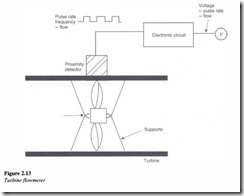
Figure 2.13 is a simple illustration of a turbine-type flowmeter.
This flowmeter has a turbine rotor in the housing, which is connected to the pipeline whose flow rate is to be measured. When the fluid flows, it causes the turbine to rotate. Higher the flow rate, greater is the speed of the turbine. The magnetic end of a sensor, which is positioned near the turbine blades, produces a magnetic field whose magnetic lines of force are interrupted by the rotation of the turbine blades, thereby generating an electrical impulse. An electrical device connected to the sensor converts the pulses to flow rate information.
Orifice plate-type flowmeter
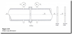
Another method by which flow rate can be determined involves the use of an orifice plate-type flowmeter in which an orifice is installed in the pipeline as shown in Figure 2.14.
The figure also shows the presence of two pressure gages, one each on either side of the orifice. This arrangement enables us to determine the pressure drop (M) across the
orifice when the fluid flows through the pipe and given by M = P1 – P2 • The higher the flow rate, greater will be the pressure drop.
The actual flow rate can be determined by the following equation:
Where
Q is the flow rate in m3/s
C is the flow coefficient (C = 0.80 for a sharp-edged orifice and 0.60 for a square-edged orifice) A is the area of the orifice opening in m2
S is the specific gravity of the flowing fluid and M = P1 – P 2 is the pressure drop across the orifice in psi or kPa.


