vane pumps
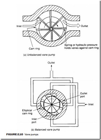
The major source of leakage in a gear pump arises from the small gaps between teeth, and also between teeth and pump housing. The vane pump reduces this leakage by using spring (or hydraulic) loaded vanes slotted into a driven rotor, as illustrated in the two examples of Figure 2.10. Centrifugal force also helps to seal the vane tips. Vane pumps are much quieter than gear pumps.
In the pump shown in Figure 2.10a, the rotor is offset within the housing, and the vanes constrained by a cam ring as they cross inlet and outlet ports. Because the vane tips are held against the housing there is little leakage and the vanes compensate to a large degree for wear at vane tips or in the hous-
ing itself. There is still, however, leakage between rotor faces and body sides. Pump displacement is determined by vane throw, vane cross-sectional area and speed of rotation. Pump displacement can again be increased by having multiple pump assemblies driven from a single shaft and motor. Many manufacturers build vane pumps with pump assemblies as replaceable cartridges which can be quickly changed.
The difference in pressure between outlet and inlet ports creates a severe load on the vanes and a large side load on the rotor shaft which can lead to bear- ing failure. The pump in Figure 2.10a is consequently known as an unbalanced vane pump. Figure 2.10b shows a balanced vane pump. This features an ellipti- cal cam ring together with two inlet and two outlet ports. Pressure loading still occurs in the vanes but the two identical pump halves create equal but opposite forces on the rotor, leading to zero net force in the shaft and bearings. Balanced vane pumps have much improved service lives over simpler unbalanced vane pumps.
Displacement and pressure ratings of a vane pump are generally lower than gear pumps, but reduced leakage gives an improved volumetric efficiency of around 95%.
In an ideal world, the displacement of a pump should be matched exactly to load requirements. Expression 2.2 showed that input power is proportional to system pressure and volumetric flow rate. A pump with too large a displace- ment wastes energy (leading to a rise in fluid temperature) as excess fluid passes through the pressure relief valve.
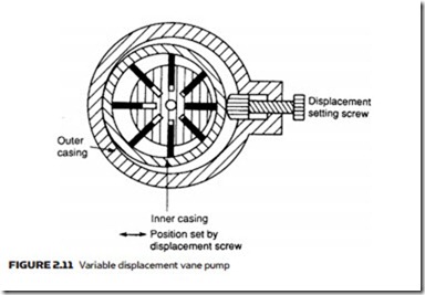
Pumps are generally sold with certain fixed displacements and the user has to choose the next largest size. Figure 2.11 shows a vane pump with adjustable displacement, set by the positional relationship between rotor and inner casing, with the inner casing position set by an external screw.

