Specification of air movers
The operating performance of compressors and exhausters, for a particular model, is generally in terms of the volumetric flow rate of the air and the delivery pressure, or vacuum, for a range of rotational speeds, similar to those presented in Figures 6.5 and 6.6. Different models will cover a different range of duties, and there is likely to be an overlap in volumetric flow rate capability between different models.
As air is compressible, with respect to both pressure and temperature, it is necessary to specify reference conditions for air movers, that are internationally recognized. It is essential, therefore, that it should be realized that the volumetric flow rate to be specified for the air mover will not be same as the volumetric flow rate required to convey a material at the start of a pipeline.
It will be necessary to convert the volumetric flow rate required for the system to the volumetric flow rate to be specified for the air mover. The air mass flow rate will be exactly the same for the two, but this is not how air movers are specified. It would provide a useful check, however, if the air mass flow rate was to be evaluated for the two cases. All the models required for this type of analysis are presented in Chapter 9 on Air Flow Rate Evaluation.
Blowers and compressors
The specification of machines delivering air at positive pressures is in terms of the volumetric flow rate of the air drawn into the machine and the delivery pressure at which the air is required. The pressure and temperature of the air, for which the volumetric flow rate applies, is generally free air conditions. This is usually taken as being a pressure of 101.3 kN/m2 absolute and a temperature of 288 K (15°C). The situation is sum- marized in the sketch below:
The pressure to be specified for the compressor is p1. This is approximately the pressure of the air required at the material feed point into the pipeline. This will depend upon the flow rate of material to be conveyed, the conveying distance, pipeline routing and the conveying characteristics of the material. An allowance will need to be made for any losses in air supply lines, pressure drop across the feeder and filtration unit, possible surges in feed rate, and a margin for contingencies and safety.
Volumetric flow rate
The volumetric flow rate to be specified is V0. This is the volumetric flow rate of free air that is drawn into the compressor. The critical design parameter for a pneumatic conveying system is the conveying line air velocity, C1, at the material feed point into the pipeline. This is the starting point in evaluating and so a value of C must be specified.
Equation (9.10) from Chapter 9 on air flow rate evaluation can be used to determine V0, knowing C1, the pipeline bore, d, the air pressure, p1, and the air temperature, T1. This is reproduced here as Equation (6.1) for reference. The constant, 2.23, takes account of the reference, free air, values of pressure and temperature required at the compressor inlet:
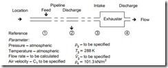
The specification of machines operating under vacuum conditions is also in terms of the volumetric flow rate of air at inlet to the machine, and the temperature here is also 288 K.
The vacuum capability of the machine is specified and this generally relates to the air being discharged from the machine to standard atmospheric pressure of 101.3 kN/m2 absolute. The situation is summarized in the sketch below:
Vacuum
The vacuum to be specified for the exhauster is p3. This will depend mainly upon the pressure drop across the pipeline, (p1 – p2), necessary to convey the material at the required flow rate over the given distance. An allowance will have to be made for any other losses and margins that might need to be included, as for the compressors considered above.
Volumetric flow rate
The volumetric flow rate to be specified is V3. This is the actual volumetric flow rate of air that will be drawn into the exhauster. The critical design parameter for a pneu- matic conveying system is the conveying line air velocity, C1, at the material feed point into the pipeline. This is the starting point in evaluating and so a value of C must be specified. Equation (9.10) can be modified slightly to determine V3, knowing C1, the pipeline bore, d, the air pressures, p1 and p3, and the air temperature, T1.
The constant is now 226 because p1 is included in the equation, since the pressure at the feed point may be a little below 101.3 kN/m2 absolute.
Air leakage and ingress
Note that for positive pressure conveying systems an allowance must be made for any air leakage across the material feeding device, or any other loss of air from the system. This will have to be added to the above value from Equation (6.1), since this is only the quantity of air required for conveying the material.
In the case of negative pressure conveying systems an allowance must be made for any air leakage into the system that may occur across the material discharge device or any other gain of air into the system. This will have to be added to the above value from Equation (6.2), as this is also the quantity of air required for conveying the material only.

