Stepped pipelines
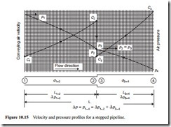
Stepped pipelines were discussed earlier in Section 9.4 to illustrate the problems of air expansion and velocity control along a pneumatic conveying system pipeline. The models necessary to evaluate the air only pressure drop have been developed since this introduction and so it is now possible to consider stepped pipelines further. A sketch of a two-section stepped pipeline is given in Figure 10.15.
Air only pressure drop
From Equation (10.12), for a single bore pipeline, the following expression was developed:
which is an expression in terms of the outlet pressure, p2.
For a stepped pipeline the total pressure drop will be equal to the sum of the individual pressure drops for each section. For a two-section pipeline the unknown pressure at the step can be eliminated by using both of the above expressions, noting that p2 = p3.
This equation is of the same form as Equation (10.42) and so the solution can either be in terms of the inlet pressure, p1, as in Equation (10.43), or in terms of the exit pressure, p4, as in Equation (10.44). The choice will depend upon which value is known, and whether the stepped pipeline is for a positive pressure or a vacuum system.
It should be noted that if the pipeline comprises more than one step, additional equations will be needed to solve the additional unknown pressures at the steps.
Position of steps
The position of the transition to a larger bore line must be such that the conveying air velocity does not drop below that of the conveying line inlet air velocity employed at the start of the pipeline. As the pressure drops along the length of the pipeline the velocity will increase, but a change in pipeline bore will significantly alter the situation, as illustrated in Figure 10.15, and with the examples shown in Figures 9.11 to 9.16 in Chapter 9 on Air flow rate evaluation.
It was also mentioned, in Section 9.4.4.1, that as a first approximation, pipeline lengths could be sized in proportion to the conveying line pressure drop for each sec- tion of pipeline, provided that a reasonably uniform value of conveying air velocity is maintained along the length of the pipeline. With reference to Figure 10.15, the length of the first section of pipeline, L1–2, would be:
The pressure at the step can be evaluated from Equation (9.13), developed in Section 9.4.1, from which the velocity at the end of each section along the length of the pipeline can be determined from either Equation (9.11), in terms of volumetric flow rates or Equation (9.20), in terms of air mass flow rate, to check on the uniformity of the velocity profile.
Transition sections
A tapered transition from one section to another would be recommended, in order to recover as much of the energy as possible in the preceding high velocity flow. The included angle of the transition would need to be about 5–10°, as shown in Figure 10.9.


