Temperature
The thermocouple
The Seebeck effect and its use in thermocouples has been outlined in section 2.4. The voltage, typically a few millivolts, is a function of the temperature difference between the measuring and the meter junction.
In practice, the meter will be remote from the measuring point. If normal copper cables were used to link the meter and the thermocouple, the temperature of the joints would not be known and further voltages, and hence errors, would be introduced. The thermocouple cables must therefore be taken back to the meter. Two forms of cable are used; extension cables which are essentially identical to the thermocouple cable or compensating cables which are cheaper and match the thermocouple characteristics over a limited temperature range.
Because the indication is a function of the temperature at both ends of the cable, correction must be made for the local meter temperature. A common method, called cold junction compensation, measures the local temperature by some other method such as a resistance thermometer and applies a correction.
Thermocouples are non-linear devices and linearizing circuits must be provided if readings are to be taken over an extended range.
Although a thermocouple can be made from any dissimilar metals, common combinations have evolved with well-documented characteristics. These are identified by single letter codes. Table 4.1 gives the details of common thermocouple types.
The resistance thermometer
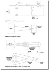
The variation of resistance with temperature in metals has been described in section 3.4.1.1. This change in resistance can be used to measure temperature. Platinum is widely used because the relationship between resistance and temperature is fairly linear. A standard device is made from a coil of wire with a resistance of 100 Ω at 0°C, giving rise to the common name of a Pt100 sensor. These can be used over the temperature range –200°C to 800°C. At 100°C a Pt100 sensor has a resistance of 138.5 Ω, and the 38.5 Ω change from its resistance at 0°C is called the fundamental interval. The current through the sensor must be limited in order to avoid heating effects. Errors from the cabling resistance can be overcome by the use of the three-wire connection of Fig. 4.20.
A thermistor is a more sensitive device comprising a semiconductor crystal whose resistance changes dramatically with temperature. Devices are obtainable which decrease or increase resistance for increasing temperature, the former being more common. The relationship is very non-linear, a typical device giving 300 kΩ at 0°C and 5 kΩ at 100°C.
Although very non-linear, thermistors can be used for measurement over a limited range, but their high sensitivity and low cost make them specially useful where a signal is required if the temperature rises above or falls below a preset value. Electrical machines often have thermistors embedded in the windings to give warning of overheating.
The pyrometer
The basis of the pyrometer is shown in Fig. 4.21. The object whose surface temperature is to be measured is viewed through a fixed aperture and part of the radiation emitted by the object falls on the temperature sensor causing its temperature to rise. The tem- perature of the object is then inferred from the rise in temperature seen by the sensor.
The sensor size must be very small, typically of the order of 1 mm diameter. Often a circular ring of thermocouples connected in series (a thermopile) is used. Alternatively a small resistance thermometer (a bolometer) may be used. Some pyrometers measure the radiation directly using photoelectric detectors.
The temperature measurement is independent of distance from the object, provided the field of view is full. Figure 4.22 shows that the source is radiating energy uniformly in all directions, so the energy received from a point is proportional to the solid angle subtended by the sensor. This decreases as the square of the distance, but as the sensor moves away the scanned area also increases as the square of the distance. These two effects cancel to give a reading which is independent of the distance.
There are various ways in which the temperature can be deduced from the received radiation. The simplest measures the total energy received from the object, which is proportional to T 4 where T is the temperature in kelvin.
A lack of knowledge of the emissivity of the surface can introduce error, but this maybe reduced by filters which restrict the measuring range to frequencies where the emissivity approaches unity. An alternative method is to take measurements at two different frequencies (that is, two different colours) and compare the relative intensities to give an indication of temperature.

