Background of AR Coating and SWG Structure
This section discusses the basic background of the AR coating and the SWG structure for the reduction of reflection losses in GaAs solar cells and the improvement in conversion efficiency of solar cells for future sustainable power systems.
Antireflection Coating
The efficiency of a solar cell can be increased by using an anti-reflection coating that reduces the light reflection losses only for certain wavelengths (such as, Infra- Red, Visible Ultra-Violet gives good performance). Minimum reflectance can be achieved when the refractive index equates to the square root of the refractive indices of two media [9]. The strength of the light reflection depends on the refractive indices of both media and the angle of the surface to the beam of light.
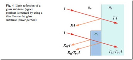
Figure 4 shows the reflection and transmission of a glass substrate with a thin film coating. Here, the light is travelling from air into a common glass substrate (upper portion). The intensity of the incident light is I, reflected light is R.I, and transmitted light is T.I. But when a thin film coating is applied on the glass substrate, it reduces the reflection of light. In this case, I is the incident light on the coating, R01 is the reflected light at the interface of air and thin film coating, and transmittance light is T01I. The incident light at the coating and glass interface is T01I, transmittance light is T1sT01I and reflectance light is R1sT01I (as shown in Fig. 4).
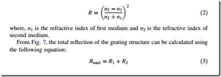
The percentage of light reflection can be calculated by using Fresnel equations
where, R is the reflection co-efficient or reflectance, n0 is the refractive index of the first media (air), and ns is refractive index of the second media (glass substrate).
For such a case, if visible light is travelling from the first media (i.e., air, n0 = 1.0) into the second media (i.e., a common glass substrate, ns = 1.5), the value of R (i.e., light reflection) is 4 %. However, when a thin film is added on the glass, it reduces the reflection loss. Then, the new optimum refractive index, n1 = H(n0ns) = H(1.0*1.5) = 1.225. The reflection loss of each interface is 1 %. i.e., the total reflection is 2 %. It was calculated that an intermediate coating between the air and the glass can reduce the reflection losses by half (about 50 %).
However, the formation of a coating film can be a complex process and there are some drawbacks such as adhesion, thermal mismatch, and instability under ther- mal cycling [9, 11].
Moth’s-Eye Principle
The surface of a moth’s eyes is covered with nano-structured film that absorbs the light instead of reflecting it back (as shown in Fig. 5). The nano-structured film consists of a hexagonal pattern bump *200 nm high, which acts as an antire- flective coating; this is because the bumps are smaller than the wavelength of visible light. The refractive index between the air and the surface changes grad- ually and this gradual change in refractive index decreases the light reflection. This model is suitable for solar cells to reduce the reflection losses and increase the conversion efficiency [13].
SWG Structure
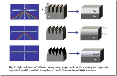
The subwavelength features cause a gradual change in refractive index which acts as a multilayer antireflective coating leading to low reflection over broadband ranges of wavelength and angle of incidence. Figure 6 shows the gradual change of the SWG structure as well as refractive index leading to the low reflection. The nanorod structure acts as a single layer AR coating, whereas the triangular (or conical) shaped SWG structure acts as a multilayer AR coating [11].
AR coating is an optical coating that is applied to the surface of lenses or other optical devices to reduce the reflection. The coating increases the efficiency of optical devices or lenses. Optimum reflection can be obtained when the refractive index equates to the square root of the refractive indices of two media [9]. Multilayer AR coatings can increase the efficiency of solar cells. However, formation of coating film can be a complex process and there are some drawbacks such as adhesion and thermal mismatch, etc., and instability under thermal cycling [8, 9].
The idea of SWG structures has been adopted from moths’ eyes. The surface of a moths’ eye is covered with nano-structured film that absorbs most of the incident
light instead of reflecting. The nano-structured film consists of a hexagonal pattern bump which is about 200 nm high. This acts as an AR coating, because the bumps are smaller than the wavelength of the visible light. The refractive index between the air and the surface changes gradually and that decreases the reflection of light. This model is being applied in solar cells to increase or improve the cell con- version efficiency [9].
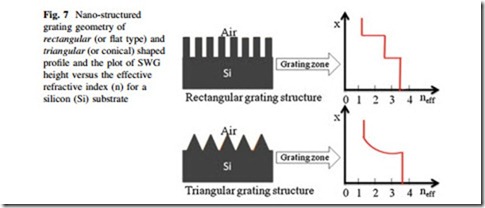
Figure 7 shows the nano-grating geometry of rectangular and triangular shaped profile and the plot of SWG height versus the effective refractive index (n) for silicon (Si) substrate [16]. It shows that for a rectangular shaped SWG structure, the refractive index changes very sharply from air (n = 1.0) to the grating zone or structure (approximately 2.5 at TM mode) [8]. The reflection loss of an SWG structure can be calculated easily using Freshnell’s equation (which is very similar to Eq. (1)),
where, R1 is the reflection at the interface of the air and the grating structure and R2 is the reflection at the interface of the grating structure and the substrate.
If the grating structure has a shorter pitch (or period) than the wavelength of the incident light, it acts as a homogeneous medium with an effective refractive index [8]. According to Fig. 7, the calculated reflection loss is more than 20.2 % for a rectangular shaped grating structure [8]. In the triangular (or conical) shaped SWG structure, the refractive index changes gradually in several steps, and the reflection becomes less than 8 % [8]. In the parabolic structure, the reflection is lower than the rectangular shaped grating structure but higher than the triangular shaped grating structure (*5 %) [15].
Geometric Shape of Nano-Gratings
This section discussed briefly the geometric shape of nano-gratings on the sub- strate of device. The SWGs are namely (i) rectangular shaped SWG structure, (ii) trapezoidal shaped SWG with different aspect ratios (i.e., 0.1, 0.2, 0.5, 0.8 and 0.9), and (iii) triangular shaped SWG structure. These shapes are shown in Fig. 8.
The aspect ratio is defined as the ratio between the top length over the base length of a trapezoid, triangle, or a rectangle. It is clear from Fig. 8 that the aspect ratio is ‘‘a/b’’, where, ‘‘a’’ is the top length and ‘‘b’’ is the base length of the geometric shapes (such as, triangle, trapezoid, and rectangle). For rectangular shaped nano-grating profile, the aspect ratio is ‘1’ (i.e., the top and base length of the trapezoid or rectangle is the same or equal) and for the triangular shaped nano- grating profile, the aspect ratio is ‘0’ (i.e., the top length of the trapezoid or rectangle is ‘0’ compared to the base length of the trapezoid or rectangle). However, for a trapezoidal shaped nano-grating the aspect ratio is 0 < (a/b) < 1, i.e., it lies between ‘0’ and ‘1’ (such as, ‘0.1’-‘0.9’). These nano-grating shapes play an important role for light trapping inside the substrate that affect the con- version efficiency of solar cells.


