New Trends on HVDC Transmission for Offshore Wind Energy
Hybrid Topologies
An alternative which has been poorly studied is to build a hybrid HVDC using a self-commutated converter, and a line-commutated converter. This hybrid topol- ogy takes advantages from force-commutated converters, i.e., VSC, as well as line-commutated converters, i.e., LCC. In the case of offshore applications, an increase in efficiency and a reduction in cost are expected.
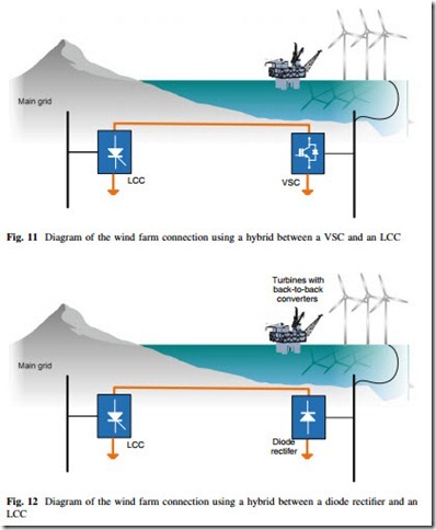
Grid integration of OWFs in [35, 36] are presented a configuration consisting of a VSC located at offshore and an LCC located onshore as shown in Fig. 11. In [35] the corresponding control strategy is stated, which is verified through numerical simulations of several conditions including: the start-up and AC faults. In [35, 37] a multiterminal approach was presented. In [38], it is proposed a hybrid with an offshore LCC and an onshore VSC. The required commutation voltage and the relatively large footprint of the offshore LCC stations are major obstacles to the implementation of this concept.
In [39] and [40], a configuration is proposed, which consists of diode-based rectifier and LCC in the same HVDC link. The concept is aimed to reduce the power losses and installation costs. A control strategy is proposed both in steady state and during transients. The concept is shown in Fig. 12.
Among current source converters some are made with self-commutating devices, denoted in this work as PWM-CSC. To date, the use of PWM-CSC has not been contemplated for HVDC applications. In [41] is presented a new hybrid configuration consisting of an LCC and a PWM-CSC as shown in Fig. 12.
In onshore applications, LCC is connected to the main grid, while the PWM-CSC is connected to an OWF at offshore side. The potential benefits of this concept include: low power losses, simple AC voltage controller, and good response to AC and DC faults. Moreover, PWM-CSC and LCC are both current sourced converters and the coupling between them can be effortlessly done.
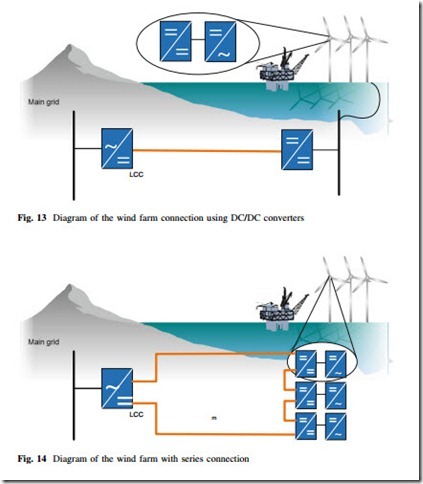
Another option was proposed in [16]. This grid topology presents different stages of conversion. The first stage of conversion is required for controlling the generators. The second and third stages of conversion are step-up DC/DC converters. The last stage of conversion is the onshore converter for grid integration of
the wind farm as shown in Fig. 13. A novel DC/DC converter with a three-phase high-frequency transformer is required in this kind of topology. Another similar concept is the dispersed converter concept with series connection [16]. This topology is schematically shown in Fig. 14.
In [16], it was found that series connection leads to the lowest grid losses.
However, the total losses are not competitive with DC parallel connections due to the losses in the converters. As a consequence of that, the efficiency of the con- verter must be improved in order to make series connection a practical alternative.
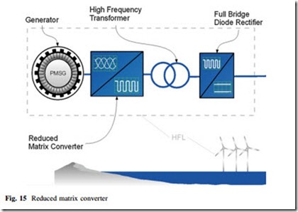
In [42], it is proposed to use an RMC which transforms the three-phase voltages and currents in a square wave, high-frequency single-phase output. A high-frequency
transformer is used for galvanic isolation and to raise the output voltage. A full- bridge diode rectifier is used as an AC/DC converter to connect the conversion system with the output DC grid. The schematic is shown in Fig. 15.
Modular Multilevel Converter
Considering the shortcomings of the classic technologies (line-commutated converters) for multiterminal operation, it is highly probable that the first developments of the ‘‘renewable energy electricity highway’’ or the so-called Super-Grid will be using VSCs. Among the different topologies of this type of converters, the modular multilevel converter (MMC) introduced by Prof. Marquardt in [43] is the most promising power converter for high-voltage/high-power applications [44–46].
The MMC is the only converter in the multilevel family that presents at the same time a modular design while having only two DC terminals suitable for HVDC transmission. Its topology allows a smooth and nearly ideal sinusoidal output voltage which requires little or no filtering at all. It is able to operate at lower switching frequencies; hence the converter losses are closer to the LCC technology [44, 45, 47]. Its modular design may lead to a reduced production cost and easier maintenance. Moreover, it has high scalability allowing a simple adjustment to the maximum voltage by increasing or reducing the number of sub- modules; and finally it has the ability to continue its operation in spite of module failure, and could be operated without the need of a transformer [48].
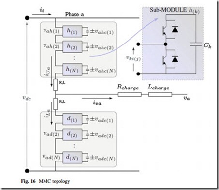
The MMC three-phase structure is shown in Fig. 16. The converter is formed by ‘‘n’’ sub-modules of which half of them are placed in the upper ‘‘arm’’ and the other half on the lower ‘‘arm.’’ Each sub-module is composed of two switches (IGBT ? diode), and basically allows two effective states: (1) a short-circuit or
(2) the appearance of the capacitor voltage between the sub-module terminals. The converter needs two-arm inductances in order to compensate voltage unbalances between the sum of the upper and lower ‘‘multi-valves’’ voltages in one phase (created by all the sub-modules), and the DC source.
The currents of the upper and lower arms may be decomposed in two inde- pendent terms each: One half of the current that will flow into the AC grid/load, and an additional current called circulating or differential current that does not flow into the load but stays ‘‘trapped’’ inside both arms of the converter, and contributes to the DC current by means of its average value. In equations:
Although the MMC topology may appear quite simple, the control task of balancing the energy stored in the capacitors while performing a stable power transfer between the DC and AC terminals is rather complex. Basically, it can be divided into two control stages: On the one hand, a fast balancing algorithm is implemented independently in each arm that will ensure that every capacitor will have practically the same voltage waveform. To do so, one must measure and sort all capacitors in the arm, and depending on the direction of the current flowing in such arm, the algorithm will select among all capacitors of the arm, the ‘‘n’’ most appropriate capacitors to be inserted, knowing that ‘‘n’’ will be given by the controller at an upper stage. On the other hand, and at a superior regulation stage, a control technique is implemented to equally distribute the energy between the arms of the converter.
Thanks to the fact that the MMC operates with two ideally independent cur- rents, two degrees of freedom are at our disposition when designing a control scheme, instead of one as is usually the case with more traditional converters. The load current is typically used to control the active power of the AC grid, while the differential current is free to be used to balance and equally distribute among each arm, the average of the energy stored in the converter.
Control methods have been proposed in order to accomplish this second task based on accurate analytical models of the MMC in state space representation (see [47, 49]). Some of the control strategies have been implemented by means of a coordinate transform, where instead of controlling the differential current in its natural phase ‘‘abc’’ coordinates, it has been controlled in the stationary ‘‘ab0’’ or even in the rotating ‘‘dqo’’ coordinates, which result from Clarke’s or Park’s respective transform (e.g., [50–52]).
Nonetheless, it seems to be getting clear that there are significant disadvantages when the control is not designed in the natural ‘‘abc’’ phase coordinates (unlike classical converters) since the complete phase-independent control of the converter state variables is not possible, hence the MMC potential will not be fully exploited. In [53] a control scheme in ‘‘abc’’ coordinates based on mathematical optimization by means of Lagrange’s multipliers was presented to overcome this obstacle, by extending the work previously done in [54, 55].
Furthermore, such promising results were extended to the MMC-HVDC case, shown in Fig. 17, under unbalance operation in [56]. With this controller the MMC acts as a ‘‘power oscillation firewall’’ as it absorbs the power fluctuations coming from the AC side and caused by the unbalance operation, yielding a constant power output at the DC terminals in spite of the unbalance. This is particularly useful in HVDC multiterminal applications, since the terminal that is being operated under unbalanced conditions will not influence the rest of the terminals, at least not through the DC grid.
Classic converters could achieve such conditions by means of their AC load current. Nonetheless, the MMC achieves such operation by means of the differential current, leaving the load current free to attend a different task; e.g., balancing the currents at the AC side during the unbalance voltage operation. This was presented in [52, 56] using a coordinate transform; while in [57], it was achieved with natural phase ‘‘abc’’ coordinates, allowing full independent control of the averaged phase variables of the converter.


