Brushless excitation
Although some generators are still produced with brushes and sliprings to provide the rotor current as illustrated in Fig. 5.4, most now have a brushless excitation system.
The two main techniques for synchronous generators are the separate exciter and capacitor excitation and these are described in the following sections. Also included for convenience here is a brief description of induction generators, since these also provide a brushless system.
Separate exciter
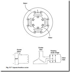
The most common way of supplying dc current to the rotor winding without brushes and sliprings is shown in Fig. 5.17.
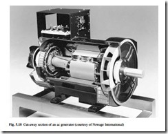
The output of the AVR drives a dc current If through the pole windings of the exciter, which are mounted in a stator frame. The poles produce a stationary field which induces a voltage in the exciter rotor winding as it turns. Figure 5.18 shows that the exciter rotor is mounted on the same shaft as the main generator. The ac voltage produced by the rotor winding of the exciter is converted to dc by a bridge rectifier which is also mounted on the rotor shaft. This rectifier unit is shown clearly at the end of the shaft in Fig. 5.23. The dc output of the rectifier is connected to the main rotor windings by conductors laid in a slot along the rotor shaft. The inductance of the main generator rotor coils is usually sufficient to smooth out the ripple in the bridge rectifier output.
The power supply to the AVR is either provided by a separate excitation winding in the main generator stator, or by a small permanent-magnet generator mounted on the shaft of the main generator, often referred to as a ‘pilot exciter’. The advantage of the pilot exciter is that the generator has a source of power available once the shaft is turning; the voltage supplied to the AVR is completely independent of generator load and there is no reliance on residual flux in the magnetic circuit of the main generator to start the self-excitation process. The pilot exciter also enables the generator to supply current to a connected network even when a short circuit occurs, enabling the high cur- rent to be detected by protection relays which will then disconnect the faulty circuit. If the AVR is supplied from an excitation winding in the main generator stator, the supply voltage is very small when the stator windings experience a short circuit, and the AVR is unable to drive an adequate rotor excitation current.
One manufacturer uses two excitation windings to provide a voltage from the AVR under short-circuit conditions, so that sufficient current is supplied into the fault to trip the protection system. During a short circuit the airgap flux density in these machines shows a pronounced harmonic component. This component induces voltage in coils of one of the excitation windings, which are short pitched and therefore deliver a
voltage to the AVR even under short-circuit conditions. The second excitation winding is fundamental-pitched and provides the major drive for the AVR under normal operating conditions. It is claimed that the performance of this system is comparable to a machine using a permanent-magnet exciter.
Another method used to provide voltage to the AVR under short-circuit conditions is a series transformer driven by the generator output current.
Capacitor excitation
The use of this technique is usually restricted to single phase generators with a rated output less than 10 kW.
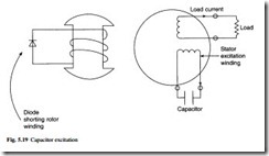
A separate excitation winding in the stator has a capacitor connected directly across its output as shown in Fig. 5.19. The rotor is usually of salient-pole construction as described previously, but in this case the rotor winding is shorted through a diode. On starting, the residual flux in the rotor body induces a small voltage in the stator excitation winding and a current flows through the capacitor. This current produces two waves of magnetic flux around the air gap of the generator. One wave travels in the same direction as the rotor, to create the armature reaction described in section 5.3.2. The second wave travels in a direction opposite to the rotor, and induces a voltage in the rotor windings at twice the output frequency. The current circulated in the rotor windings by this induced voltage is rectified by the diode to produce a dc current. This dc current increases the magnetic flux in the machine, which in turn drives more current through the stator excitation winding, which in turn produces more rotor cur- rent. This self-excitation process continues until the flux reaches a point at which the
magnetic circuit is saturated, and a stable voltage results. The process also produces an inherent AVR action, since any load current in the output stator winding induces more rotor current to offset the armature reaction effect.
Induction generator
The principles of the cage induction motor are explained in Chapter 10. If a machine of this type is connected to a supply, it accelerates as a motor up to a speed near its synchronous speed. If the machine is driven faster than the synchronous speed by an engine or other prime mover, the machine torque reverses and electrical power is deliv- ered by the machine (now acting as a generator) into the connected circuit.
A simple form of wind turbine generator uses an induction machine driven by the wind turbine. The induction machine is first connected to the three-phase supply, and acting as a motor it accelerates the turbine up to near the synchronous speed. At this point, the torque delivered by the wind turbine is sufficient to accelerate the unit further, the speed exceeds the synchronous speed and the induction machine becomes a generator.
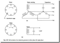
It is also possible to operate an induction machine as a generator where there is no separate mains supply available. It is necessary in this case to self-excite the machine, and this is done by connecting capacitors across the stator winding as shown in Fig. 5.20(a). The leading current circulating through the capacitor and the winding produces a travelling wave of mmf acting on the magnetic circuit of the machine. This travelling wave induces currents in the rotor cage which in turn produces the travelling flux wave necessary to induce the stator voltage. For this purpose, some machines have an excitation winding in the stator which is separate from the main stator output winding. Figure 5.20(b) shows a single-phase version of the capacitor excitation circuit.
In small sizes, the induction generator can provide a low-cost alternative to the syn- chronous generator, but it has a relatively poor performance when supplying a low power factor load.
Although induction generators have useful characteristics for use in combination with wind turbines, the magnetizing current must be supplied by other generators
running in parallel, or capacitors connected across the stator windings. Another problem is that the efficiency of an induction generator drops if its speed differs significantly from the synchronous speed, due to high rotor copper loss in the rotor cage. This can be overcome by using a slipring-fed wound rotor combined with a power electronic converter connected between the stator and rotor windings. Such schemes are often referred to as slip energy recovery using a doubly fed induction generator.
The slip s, of an induction machine is the per unit difference between the rotor speed and the synchronous speed given by:
where Ns is the synchronous speed and Nr is the rotor speed. It can be shown that if Tr is the mechanical torque supplied by a turbine to the rotor of the induction generator, the generated electrical stator power transferred across the air gap is given by Tr Ns. Since the input mechanical power to the generator is Tr Nr, the difference Tr Nr – Tr Ns must be the power lost in the rotor, produced mainly by copper loss in the cage. By substitution from eqn 5.8:
With a simple squirrel cage rotor therefore the slip must be low to avoid high rotor loss with a resultant low efficiency.
If the cage is replaced by a three-phase winding, and sliprings are fitted, the same power balance can be achieved by removing the generated rotor power via the sliprings. This power can then be returned to the stator of the generator via a frequency converter. The rotor generated frequency is given by the stator frequency times slip ( f ´ s). The circuit illustrating this slip recovery is shown in Fig. 5.21. The advantage
of this scheme is that the power rating of the electronic converter from eqn 5.9 is (slip ´ stator power generated). The scheme therefore allows the speed of the wind turbine to be varied to obtain more efficient turbine operation at different wind speeds. The rating of the converter is proportional to the maximum rated slip value, typically about ± 30 per cent, where positive slip applies to subsynchronous rotor speeds. In comparison, a variable-speed, constant-frequency system using a synchronous generator would require a frequency converter rated at full generator power.
The above slip recovery system requires sliprings which can be a disadvantage in marine environments. The sliprings can be eliminated in generators using two mechanically coupled stators and wound rotors with the second stator supplied from the frequency converter. This is known as a brushless doubly fed system, but adds considerable cost to the system.
Inductor alternator
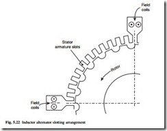
From eqn 5.5 it is evident that to achieve high frequency, either the speed or the pole number of the generator must be high. The number of poles that can be considered in a conventional generator design is limited because the slots become too small and the leakage fluxes become too high. A robust construction that overcomes these problems is known as the inductor alternator, and one configuration is shown in Fig. 5.22.
In this quarter cross section the field windings are inserted into the large stator slots and produce a stationary four-pole flux pattern. The armature coils are placed in the smaller slots, each coil enclosing one tooth, and connected in an alternate sense in series to form a phase. The rotor contains no windings and has double the tooth-pitch of the stator. With the rotor in the position shown, the rotor teeth line up with the odd numbered stator slots, and the flux driven by the field coils will flow through this low reluctance path linking the coils round these teeth. The even numbered teeth experience a low flux level. If the rotor is now moved one stator tooth pitch, the high flux will now link the even numbered coils and the stator windings experience an alternating flux linkage and generate an alternating voltage. Unlike the synchronous genera- tor, the stator teeth and air gap experience flux in one direction only. The flux varies
from a maximum to a minimum in one direction, while the synchronous machine experiences a reversal in flux direction. This results in a lower effective magnetic loading, and power density. Numerous slotting arrangements have been devised in order to ease winding and minimize losses and reactances for particular duties.
Related posts:
Incoming search terms:
- Excitation controller
- Capacitor for generator excitation
- Generators mail
- brushless generator
- residue current in bruahles generaomtor
- exciter winding brushless generator
- excite a generator
- brushless ac generator
- how to calculate nessicary coil and capacitor size for brushless generator
- brushless motor connected to power supply is blowing capacitors
- how does a alternator lose excitation
- what voltage is use to excite a home generator
- capacitor compensated brushless generator
- avr brush excitation
- WHAT IS THE smallEST generator with brushless excitation
- self excited generator theory
- exciter circuit for brushless ac generator
- brushless capacitor excited generator
- power generators mail
- brushless self excited generator circuit
- brushless self excited error operated system
- how is brushless excitation achieved
- Exciter coil connection to the AVR
- function of capacitor in generator
- brushless generator diagram
- function of generator capasitor
- Brushless Motor mail
- genator coilsnd excster /coil
- portable generator rotor winding capaciyor excite
- pilot exciter synchronous generator
- bruchless generator of 60kva 415v how to construct the AVR to the execited coil
- are dpe and power windings in a standby generator the same
- how a brushless capacitor generator works
- Power Generation mail
- brushless dc generator
- generator coil current system
- Capacitor mail
- Alternative Energy Generators mail
- purpose of generator winding capacitor
- generator brush rotor capacitor
- 1700KW brushless ac generator no output voltage
- avr to excitor coil
- avr with self excitation generator
- blussless exitation
- brushless exciter pilot ac winding configuration
- brushless excitation
- brushless Excitation coil diagram of Gen
- brushless exciter
- brushless exciter diagram
- brushless double excitation system
