Conventional Generator Layout
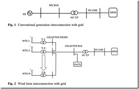
Figure 1 illustrates the philosophy of conventional generator layout and its connection to the power system. A conventional generator normally generates at a relatively higher voltage level compared to wind farms, for instance 11–15 kV, thus directly connecting to a medium voltage (MV) level bus as shown in the figure. The voltage is further stepped up through a high voltage (HV) transformer to connect to grid through HV transmission link. The actual arrangement for relatively smaller generation units may vary but large conventional generation units generally follow this arrangement.
Wind Farm Layout
Figure 2 illustrates the philosophy of wind farm layout and its connection to the grid. A wind farm comprises multiple wind units varying from a few to hundreds in number. Each WTG normally generates at a relatively lower voltage (LV) level compared to wind farms, for instance 400 or 690 V; thus directly connecting to an LV level bus called collector feeder as shown in Fig. 2. Each collector feeder may have one or few units connected to it in parallel. The voltage from these collector feeders is then collected to collector bus to achieve aggregated power from all
turbines at the same time. Collector bus voltage is then further stepped up through HV transformer to connect it to grid through HV transmission link. The flexible alternating current transmission systems (FACTS) devices such as static VAR compensators (SVCs) and static synchronous compensator (STATCOMs) are generally connected at the collector bus but they may vary in location in the real practice. The actual arrangements differ but most of the installed wind farms globally follow this arrangement.
