Battery Service Test (Load Test)
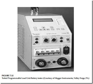
A service test of the battery is normally made to satisfy that the battery can meet its load profile, that is, its duty cycle. This test is also known as load cycle test. When a service test is conducted on a regular basis, it will indicate whether the battery indeed can perform its intended function. Therefore, this test may be conducted on an annual basis. Trending battery voltage during the critical periods of the load test can provide information when the battery will no longer meet its design requirements. In IEEE standard 450-2002 and IEEE standard 1188-2005, this test is referred to as service test and it is recommend that this test be conducted between the cycle of the performance tests. When a service test is also being used on a regular basis it will reflect maintenance practices and the health of the battery to meet its design requirements. When a battery shows signs of degradation, service testing should be continued to be performed on its normal frequency. Several manufacturers have built programmable battery load testers and market them for conducting the service (load) test. The Torkel Programmable Load Unit Battery load tester, manufactured by Megger Instruments is shown in Figure 7.32.
Connection Resistance Test
The connection resistance of the intercell connections and terminal connec- tions can be made with the use of digital low-resistance ohmmeter to assess the integrity of the current (conduction) path. Normal connection resistance varies with the cell size and connection type, and ranges from less than 10 μΩ for a large battery to as much as 100 μΩ for a smaller battery. Periodic mea- surements should be made, such as annually, and compared to previous years value to determine the need for corrective action for maintenance. A 20% change from the previous years baseline values, or values that exceed the manufacturer’s limits should initiate the need for corrective action. Refer to IEEE standard 450-2002 for more details on this method.
Battery Impedance Test
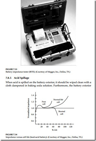
This test is based on the principle that the electrical properties of the battery, such as impedance changes proportionally with a battery’s age and discharge history. The relative internal impedance of a cell increases due mainly to losses of active material as its capacity decreases. As the cells age naturally, a life curve can be plotted for a cell and compared to a generic curve of similar cell to indicate degradation or life expectancy. The intercell impedance can be measured by using a low-frequency current source. The object of the test is to pass current through the battery string and measure the resultant voltage drop across each cell, and then compute the cell impedance. This test can be performed during float conditions without disconnecting the battery. The impedance tester, manufactured by Megger Instruments is shown in Figure 7.33. When interpreting test results, it should be noted that change in cell imped- ance is also affected by other factors, such as temperature, state of the charge, load conditions, or combination of all these. These conditions should be monitored and recorded before making measurements.
Impedance readings for the individual cells can be used in the short-term to compare with the average impedance reading for the entire battery. Individual cell values that vary by more than ±20% of the battery average typically indicate a problem with that cell. Impedance readings of the entire battery can be used in the long-term to determine the need for replacement. Battery cell impedance values should be recorded and compared to previous readings to determine the position of the cell on the curve of impedance versus cell life. A sample curve for a generic lead–acid cell is shown in Figure 7.34. Curves may differ for other man- ufacturer batteries and battery chemistries. The reader may want to consult Megger Instruments who maintains a database of cell impedance values for many battery manufacturers at various temperatures, applications, and cell age.
Addition of Water
Due to charging, the battery will normally lose water through evaporation and chemical action. Distilled water must be added to the battery, preferably before the equalizing charge is applied.
should be wiped dry after wiping with a water-dampened cloth following the initial cleaning.
Loose Connections
Battery terminal connections and intercell connections should be checked periodically as discussed in Section 7.8.3.4.
Corrosion
All corrosion on battery terminals should be removed by applying baking soda solution and the terminals cleaned by using a brass brush. Antioxidant coating should be applied before reconnecting.
Other Maintenance Hints
• Do not ground the electric storage battery, because a second acciden- tal ground on the ungrounded polarity of any circuit fed by the battery would cause the control circuit fuse to blow
• New batteries after initial charge should be kept on float charge for a week
• Take weekly readings of the voltage of selected cells and total battery voltage
• Take monthly readings of electrolyte level, cell voltage, specific gravity, and temperature
• Every 3 months to 1 year, take a complete set of cell readings

