The Automatic Voltage Regulator (AVR)
While some small generators have an inherent ability to produce a reasonably constant voltage as the load varies, it is clear from the previous explanations that some form of automatic voltage control is required in the usual form of generator. The Automatic Voltage Regulator (AVR) already referred to in the preceding sections is based on a closed-loop control principle.
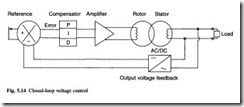
The basis of this closed loop control is shown in Fig. 5.14. The output voltage is converted, usually through a transformer or resistor network, to a low voltage dc signal, and this feedback signal is subtracted from a fixed reference voltage to produce an error signal.
The error signal is processed by a compensator before being amplified to drive the rotor excitation current. The change in rotor excitation current produces a variation in output voltage, closing the control loop. If the gain of the control loop is large enough then only a small error is required to produce the necessary change in excitation current, but a high gain can lead to instability in the circuit, with oscillations in the output voltage. The purpose of the compensating circuit is to enable small errors to be
handled in a stable way. The most common form of compensator is a PID circuit in which the error is amplified proportionately (P), integrated (I) and differentiated (D) in three parallel circuits before being added together. Many AVRs have adjustment potentiometers which allow the gains of each channel to be varied in order to achieve the best performance. The integral term enables compensator output to be achieved at zero error, and this produces the minimum error in output voltage.
The layout of a commercial AVR is shown in Fig. 5.15. Many AVRs are now offered with digital circuitry. The principle of the feedback loop remains the same, but the feedback signal is converted to digital form using an analogue-to-digital converter. The calculations are performed digitally in a microprocessor and the output is on or off, using pulse width modulation (PWM) to vary the average level of dc supplied to the rotor excitation winding. Alternatively, the phase angle of a thyristor bridge can be used to vary the output level; this is known as phase-angle control.
The continuous improvement in power electronic controls and processor power is bringing further advances in voltage and speed control, with more flexible protection of the generator and its connected circuits. An example is the variable-speed constant- frequency generator from Generac Corporation; this is illustrated in Fig. 5.16. This consists of a permanent-magnet generator driven by a variable-speed engine and feeding a power electronic frequency-changer circuit, which delivers output at constant frequency. A microprocessor is used to control the switching of the output devices and to regulate the engine speed depending upon the load applied to the generator. At low power demand the engine speed is reduced to minimize noise, increase efficiency and extend life. The result is a saving in the volume and weight of the generator.

