Two-speed motor control
At times, it is required to run equipment at two different speeds. This is usually so in certain industrial applications, such as mixer motor speeds, ventilating pumps, and batch control processes. Particularly in batch control, while feeding the batch components in a mixer, these components are fed into the mixer at two different feed rates – fast coarse feeding and slow fine feeding. This is done to feed the components accurately and to avoid overshoots. To achieve this, two-speed motors are employed.
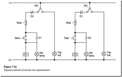
A typical control circuit for a two-speed motor is shown in Figure 7.16. There are two electrically separate windings housed in the motor. The control circuit connects the windings in different configurations causing the speed to change from one rpm to another. Each winding can deliver the motor’s horsepower at a rated speed.
As shown in Figure 7.16, two contactors are incorporated for low and high rpm. They should not be activated at the same time electrically. To protect both of them separately,
an independent overload relay protection is provided.
Overload protection
Protection is provided to protect the motor from excessive overheating due to a motor overload. The overload protection protects the motor from excessive loading and at the same time protects starter components and conductors from overheating.
The working principle being, to sense the current flowing through the motor, that being a direct measure of heating and load to the motor. For overload protection in a motor
circuit, bimetal relays are commonly used. The bimetal relays are triple-pole adjustable overload relays with built-in single-phasing protection. They provide accurate and reliable protection to the motors against overload and single phasing.
The bimetal relays provide an accurate overload and accelerated single-phasing protection for the motors. They incorporate the duel slider principle for accelerated tripping under the single-phasing protection. They also provide protection against severe unbalanced voltages.
The thermal relay is connected in series with the motor conductors, as excessive current passes through it for a preset time interval, a contact (in series) gets operated resulting in a motor trippage. The relay has settings (generally 3–14% of full load current) for various current ratings of the motor. These can be set accordingly.
Following the curve of a thermal overload, the relay shows the relationship between current and time. The relay will not trip at a rated current, but at twice the rated current after a time duration of 45 s approximately. The bimetal relays protect themselves against overloads of up to 10 times the maximum setting. Beyond this limit, they have to be protected from short-circuits. It is mandatory to use backup fuses for this purpose. The typical operating characteristics of bimetal relays are shown in the Figure 7.17.
In high intertia drives, the starting time of the motor may be high (30–60 s). Use of standard thermal overload relays will cause the motor to trip before it achieves rated speed. In such cases, special thermal overload relays with a saturable CT may be required and are available from several vendors. A backup protection may be also provided in the form of a speed switch and a timer to detect abnormal starting condition and trip the motor.
