DRIVE CIRCUITS AND PULL-OUT TORQUE–SPEED CURVES
Users often Wnd diYculty in coming to terms with the fact that the running performance of a stepping motor depends so heavily on the type of drive circuit being used. It is therefore important to emphasise that in order to meet a speciWcation, it will always be necessary to consider the motor and drive together, as a package.
There are three commonly used types of drive. All use transistors, which are operated as switches, i.e. they are either turned fully on, or they are cut-oV. A brief description of each is given below, and the pros and cons of each type are indicated. In order to simplify the discussion, we will consider one phase of a 3-phase VR motor and assume that it can be represented by a simple series R–L circuit in which R and L are the resistance and self-inductance of the winding, respectively. (In practice the inductance will vary with rotor position, giving rise to motional e.m.f. in the windings, which, as we have seen previously in this book, is an inescapable manifestation of an electromechanical energy-conversion process. If we needed to analyse stepping motor behaviour fully we would have to include the motional e.m.f. terms. Fortunately, we can gain a pretty good appreciation of how the motor behaves if we model each winding simply in terms of its resistance and self-inductance.)
Constant-voltage drive
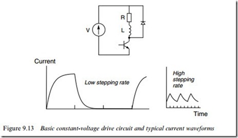
This is the simplest possible drive: the circuit for one of the three phases is shown in the upper part of Figure 9.13, and the current waveforms at low and high stepping rates are shown in the lower part of the Wgure. The d.c. voltage V is chosen so that when the transistor is on, the steady
current (equal to V/R if we neglect the on-state voltage drop across the transistor) is the rated current as speciWed by the motor manufacturer.
The current waveforms display the familiar rising exponential shape that characterises a Wrst-order system: the time-constant is L/R, the current reaching its steady state after several time-constants. When the transistor switches oV, the stored energy in the inductance cannot instantaneously reduce to zero, so although the current through the transistor suddenly becomes zero, the current in the winding is diverted into the closed path formed by the winding and the freewheel diode, and it then decays exponentially to zero, again with time-constant L/R. In this phase the stored energy in the magnetic Weld is dissipated as heat in the resistance of the winding and diode.
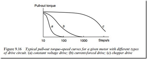
At low stepping rates (low speed), the drive provides a reasonably good approximation to the ideal rectangular current waveform. (We are considering a 3-phase motor, so ideally one phase should be on for one step pulse and oV for the next two, as in Figure 9.10.) But at higher frequencies (right-hand waveform in Figure 9.13), where the ‘on’ period is short compared with the winding time-constant, the current waveform degenerates, and is nothing like the ideal rectangular shape. In particular the current never gets anywhere near its full value during the on pulse, so the torque over this period is reduced; and even worse, a substantial current persists when the phase is supposed to be oV, so during this period the phase will contribute a negative torque to the rotor. Not surprisingly all this results in a very rapid fall-oV of pull-out torque with speed, as shown in Figure 9.16(a).
Curve (a) in Figure 9.16 should be compared with the pull-out torque under ideal constant-current conditions shown in Figure 9.12 in order to appreciate the severely limited performance of the simple constant- voltage drive.
Current-forced drive
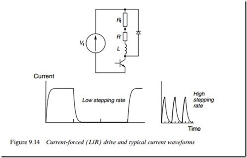
The initial rate of rise of current in a series R–L circuit is directly proportional to the applied voltage, so in order to establish the current more quickly at switch-on, a higher supply voltage (Vf ) is needed. But if we simply increased the voltage, the steady-state current (Vf /R) would exceed the rated current and the winding would overheat.
To prevent the current from exceeding the rated value, an additional ‘forcing’ resistor has to be added in series with the winding. The value of this resistance (Rf ) must be chosen so that Vf =(R þ Rf ) ¼ I , where I is the rated current. This is shown in the upper part of Figure 9.14, together with the current waveforms at low and high stepping rates. Because the rates of rise and fall of current are higher, the current waveforms approximate more closely to the ideal rectangular shape, especially at low stepping rates, though at higher rates they are still far from ideal, as shown in Figure 9.14. The low-frequency pull-out torque is therefore maintained to a higher stepping rate, as shown in Figure 9.16(b). Values of Rf from 2 to 10 times the motor resistance (R) are common. Broadly speaking, if Rf ¼ 10R, for example, a given pull-out torque will be available at 10 times the stepping rate, compared with an unforced constant-voltage drive.
Some manufacturers call this type of drive an ‘R/L’ drive, while others call it an ‘L/R’ drive, or even simply a ‘resistor drive’. Often, sets of pull- out torque–speed curves in catalogues are labelled with values R/L (or L/R) ¼ 5, 10, etc. This means that the curves apply to drives where the forcing resistor is Wve (or ten) times the winding resistance, the implication being that the drive voltage has also been adjusted to keep the static current at its rated value. Obviously, it follows that the higher Rf is made, the higher the power rating of the supply; and it is the higher power rating which is the principal reason for the improved torque– speed performance.
The major disadvantage of this drive is its ineYciency, and the con- sequent need for a high power-supply rating. Large amounts of heat are dissipated in the forcing resistors, especially when the motor is at rest and the phase current is continuous, and disposing of the heat can lead to awkward problems in the siting of the forcing resistors.
It was mentioned earlier that the inXuence of the motional e.m.f.
in the winding would be ignored. In practice, however, the motional e.m.f. always has a pronounced inXuence on the current, especially at high stepping rates, so it must be borne in mind that the waveforms shown in Figures 9.13 and 9.14 are only approximate. Not surprisingly, it turns out that the motional e.m.f. tends to make the current wave- forms worse (and the torque less) than the discussion above suggests. Ideally therefore, we need a drive, which will keep the current constant throughout the on period, regardless of the motional e.m.f. The closed-loop chopper-type drive (below) provides the closest ap- proximation to this, and also avoids the waste of power, which is a feature of R/L drives.
Chopper drive
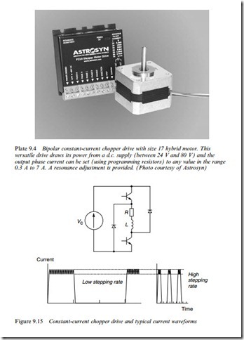
The basic circuit for one phase of a VR motor is shown in the upper part of Figure 9.15 together with the current waveforms. A high-voltage power supply is used in order to obtain very rapid changes in current when the phase is switched-on or oV.
The lower transistor is turned on for the whole period during which current is required. The upper-transistor turns on whenever the actual current falls below the lower threshold (shown dotted in Figure 9.15) and it turns oV when the current exceeds the upper threshold. The chopping action leads to a current waveform that is a good approximation to the ideal (see Figure 9.10). At the end of the on period both transistors switch oV and the current freewheels through both diodes and back to the supply. During this period the stored energy in the
inductance is returned to the supply, and because the winding terminal voltage is then -Vc, the current decays as rapidly as it built up.
Because the current-control system is a closed-loop one, distortion of the current waveform by the motional e.m.f. is minimised, and this means that the ideal (constant-current) torque–speed curve is closely followed up to high stepping rates. Eventually, however, the ‘on’ period reduces to the point where it is less than the current rise time, and the full current is never reached. Chopping action then ceases, the drive reverts essentially to a constant-voltage one, and the torque falls rapidly as the stepping rate is raised even higher, as in Figure 9.16(c). There is no doubt about the overall superiority of the chopper-type drive, and it is gradually becoming the standard drive. Single-chip chopper modules can be bought for small (say 1–2 A) motors, and complete plug-in chopper cards, rated up to 10 A or more are available for larger motors.
The discussion in this section relates to a VR motor, for which unipolar current pulses are suYcient. If we have a hybrid or other permanent magnet motor we will need a bipolar current source (i.e. one that can provide positive or negative current), and for this we will Wnd that each phase is supplied from a four-transistor H-bridge, as discussed in Chapter 2, Section 2.4.1.
Resonances and instability
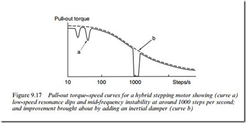
In practice, measured torque–speed curves frequently display severe dips at or around certain stepping rates. Manufacturers are not keen to stress this feature, and sometimes omit the dips from their curves, so it is doubly important for the user to be on the look out for them. A typical measured characteristic for a hybrid motor with a voltage-forced drive is shown as (a) in Figure 9.17.
The magnitude and location of the torque dips depend in a complex way on the characteristics of the motor, the drive, the operating mode and the load. We will not go into detail here, apart from mentioning the underlying causes and remedies.
There are two distinct mechanisms that cause the dips. The Wrst is a straightforward ‘resonance-type’ problem, which manifests itself at low stepping rates, and originates from the oscillatory nature of the single- step response. Whenever the stepping rate coincides with the natural frequency of rotor oscillations, the oscillations can be enhanced, and this in turn makes it more likely that the rotor will fail to keep in step with the advancing Weld.
The second phenomenon occurs because at certain stepping rates it is possible for the complete motor/drive system to exhibit positive feed- back, and become unstable. This instability usually occurs at relatively high stepping rates, well above the ‘resonance’ regions discussed above. The resulting dips in the torque–speed curve are extremely sensitive to the degree of viscous damping present (mainly in the bearings), and it is not uncommon to Wnd that a severe dip, which is apparent on a warm day (such as that shown at around 1000 steps per second in Figure 9.17) will disappear on a cold day.
The dips are most pronounced during steady-state operation, and it may be that their presence is not serious provided that continuous operation at the relevant speeds is not required. In this case, it is often possible to accelerate through the dips without adverse eVect. Various special-drive techniques exist for eliminating resonances by smoothing out the stepwise nature of the stator Weld, or by modulating the supply frequency to damp out the instability, but the simplest remedy in open- loop operation is to Wt a damper to the motor shaft. Dampers of the
Lanchester type or of the viscously coupled inertia (VCID-type) are used. These consist of a lightweight housing, which is Wxed rigidly to the motor shaft, and an inertia, which can rotate relative to the housing. The inertia and the housing are separated either by a viscous Xuid (VCID-type) or by a friction disc (Lanchester type). Whenever the motor speed is changing, the assembly exerts a damping torque, but once the motor speed is steady, there is no drag torque from the damper. By selecting the appropriate damper, the dips in the torque–speed curve can be eliminated, as shown in Figure 9.17(b). Dampers are also often essential to damp the single-step response, particularly with VR motors, many of which have a highly oscillatory step response. Their only real drawback is that they increase the eVective inertia of the system, and thus reduce the maximum acceleration.
