Output contacts
Normally Open contact terminals 5 and 6. When CR1 is energized, the contact will close and open the dampers.
Normally Open contact terminals 7 and 8. When CR1 is energized, the contact will close and close the digital input to DGH1, which will communicate to the PLC over the RS-485 network, and the PLC can react and run the required program.
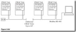
Figure 4-8d is an example of a typical RS-485 multipoint network with the Modbus protocol. The CRAC units can communicate their set- tings to the host computer using the Modbus protocol.
Kilowatt Meter
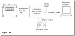
Figure 4-8e shows the typical use of a monitoring network. It is used here to collect data from the kilowatt meter and send them to the host computer.
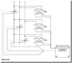
Figure 4-8f shows the use of current and control transformers to col- lect the data needed by the kilowatt meter.
Ethernet Introduction and Specifications
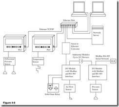
Ethernet is a computer networking technology for local-area networks (LANs). Ethernet is the most widely used network topology. Typical network speeds are 10 to 100 Mbit/s. The most commonly used configu- ration is 10 BASET 10 Mbps which runs over four wires (two twisted pairs) on CAT3 or CAT5 cable. As shown in Fig. 4-9, a hub or switch sits in the middle of the network and has a port for each node. This configu- ration is also used for 100 BASET 100 Mbit/s and gigabit Ethernet a gigabit per second. The Ethernet network uses TCP or TCP/IP. TCP is Transmission Control Protocol and IP is Internet Protocol.
Ethernet is typically used for the backbone of the network. The high speeds of Ethernet are not required for monitoring applications. The cost of the Ethernet port prenode network makes it cost-prohibitive for the data collection part of the network. It is more cost-effective to use RS-232 or RS-485 than to convert to Ethernet to join the network.
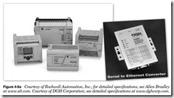
A commonly used method to convert from RS-232 or RS-485 is to use a PLC such as the Allen Bradley Micrologix 1100 or modules like the A3000 from DGH Corporation. These methods are pass-through devices so that the protocol used on the serial network will be passed to the host network. This allows them to use ASCII or Modbus protocols. (See Fig. 4-9a.)
Universal Serial Bus
Universal serial bus (USB) is a serial bus standard for the connecting of devices to a host computer. USB was designed to replace serial, parallel, and small computer system interface (SCSI). It allows many peripherals to be connected using a standardized interface socket and standard drivers. USB also allows for the ability to hot-swap devices, connecting and disconnecting devices without rebooting the computer or turning off the device. The USB 2.0 specification has a data transfer rate up to 480 Mbit/s.
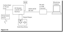
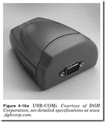
There are means to convert from RS-485 to USB such as the one in Fig. 4-10a from DGH Corporation.
