Keypads
The keypad type of switch, used either as the small numerical keypad or as the full-blown alphanumeric computer keyboard, is usually mechanically simple and requires debouncing circuitry or software. The switch is usually arranged so that contact is made about halfway along the travel of the key, and a spring is used to impart some ‘feel’ to the keyboard and to prevent the contacts from being pushed together with excessive force by the sort of typing that is more thump than touch in nature. Just as the mechanical quality of the switches can vary from the simple phosphor-bronze leaves to the Hall-effect magnetic, so the electronics of the keyboard can range from simple matrix to the completely debounced and decoded. The basic keyboard, however, is always connected using on/off switches in a matrix pattern.
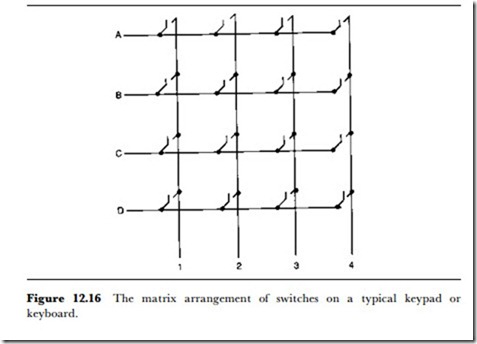
The basis of a matrix keyboard is illustrated in Figure 12.16. The keys are arranged in lines and columns, and each switch will have one connection made to a line and the other to a column. This greatly reduces the cabling to the keyboard, because an array of 64 switches in an 8 x 8 matrix needs only 16 connections. The matrix arrangement, incidentally, applies only to the electrical connections – the physical arrangement of the keys on the keyboard can be anything that is required by the designer, although very
few keyboards depart from the calculator or telephone pad style for numeric, or the typewriter arrangement for alphanumeric use.
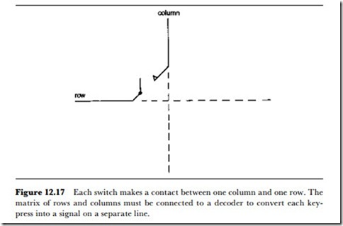
Because of the matrix connection, the closure of a key does not have the effect of a conventional switch in causing connection between two points that are unique to that switch. In a switch matrix, each row or column wire will be used by more than one switch, and the closure of one switch will cause a connection between one row and one column (see Figure 12.17). This particular combination will often be unique to that switch, although on some arrangements the simultaneous pressing of two keys can produce a false output: for example, on an old PC keyboard, careless pressing of OM can produce OM7. A matrix keyboard or keypad is therefore of little use in its natural state and needs to be decoded, in the sense that combinations of connections between rows and columns have to be translated into signals that are related to the keys.
The decoding is usually carried out in the keyboard itself, using a matrix IC, and when this is done the keyboard is sometimes described as decoded, intelligent or smart. Using decoding, or at least partial decoding, at the keyboard allows the connection to the computer to be made using a simple serial link. This is why it is so easy to convert a keyboard termination between the usual choice of Serial or PS/2 by means of a simple adapter, since both use the same signal methods. Now that keyboards use at least 102 keys, this serial connection is essential to avoid bulky cables between the keyboard and the computer. A later form of serial connection, USB (Universal Serial Bus) is now becoming common for keyboard and other connections.
• Vhen the keyboard or keypad is part of a computer system, the decoding will invariably be carried out by software, and this software will include the key debouncing circuits and provision for making the key action repeat if the key is held down.
Vhere a keypad is used in equipment that does not include a micropro- cessor (now rapidly becoming an endangered species) a decoder IC can be used. The use of such ICs provides much more than simple key detection, and it would be difficult to justify the use of any other method of decoding. Just to give one example, even a low-cost decoder could be expected to provide effective debouncing and also key roll-over. This latter term means that if two keys are struck in rapid succession, the output of the decoder will be the signal for the first key struck, followed at an interval by the signal for the second; simple decoders will usually give a false signal for such an event. In addition, the decoder will usually incorporate a latch circuit that stores the result of a key closure even after the key has been released. This allows the main system to poll the decoder at intervals that are not synchronized with the pressing of the keys.

