Introduction
The piston system involves all those parts which transmit the power of combustion to the flywheel. ‘ These parts are the piston assemblies, connecting rods, main and rod bearings, crankshaft, vibration damper, flywheel, cylinder block and cylinder head.
It should be realized that most repairs to the piston system are made for the purpose of reduc ing oil consumption or to eliminate objectionable noise. When parts become very loose and noisy, new parts may be necessary to forestall breakage. Worn parts are not likely to greatly affect fuel economy and power.
Obviously, to do repair work on the piston system, it is necessary to remove the cylinder head and oil pan. Some jobs require the removal of the engine-Corvair, for example.
After the cylinder head has been taken off, it should be cleaned and then the head and block should be examined for cracks, warpage, leakage and other defects.
If the complaint is high oil consumption or if loose main, rod or camshaft bearings are sus pected, it is a good plan to check the bearings with an oil leak detector before removing the pistons. Excess oil leaking out of loose bearings is thrown on the cyIinder walls by the whirling crankshaft, increasing the oil consumption. New rings will not bring oil consumption down to normal if main, rod or camshaft bearings leak too much.
The procedure for making a bearing leak test is given in the Crankshaft and Bearings Chapter.
In a new engine, the bores are straight, circular holes. Variation in straightness of the bore from top to bottom is only a fraction of a thousandth of an inch. And likewise the bores are circular within a fraction of a thousandth. Therefore the pistons slide up and down over almost perfectly straight surfaces and the rings press out against almost perfectly circular bores.
Each piston moves up and down about 3,000 times per mile in a typical car or 30 million times in 10,000 miles. So in spite of good lubrication, wear is bound to occur. The piston rings cause more wear than the pistons. They are springy and arc designed so that they press outward against the bore in order to seal off the hot, high pressure gases in the combustion chamber as well as to prevent oil from flowing past the rings into the combustion chamber.
Most of the cylinder bore wear occurs at its upper end where the rings scrape up and down on the bore surface. By contr ast, th e smooth piston skirt causes very slight wea r in the lower end of the bore. Hence, the bore gradually becomes tapered, being larger in diameter at the upper end than at the lower.
CYLINDER BORE WEAR
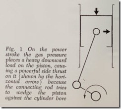
Bores wear more rapidly crosswis e of the engine than fore and aft. This is because there are power ful side thrusts by the pistons as they move up and down. Fig. 1 shows a piston m oving down ward on its power stroke. The total f orce (due to gas pressure) pushing down on the piston is a ton or two and this force jams the piston h ard against the bore as shown by the horizontal arrow.
Side thrusts, obviously, are due to the angu larity of the connecting rod with respect to th e piston. Side thrust is absent only when the piston is at top and bottom dead center. There is no side thrust lengthwise of the engine because there is no connecting-rod angularity. The inertia forces act ing on the piston also produce strong side thrusts.
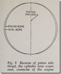
The side thrust causes the bore to wear into anoval shape, Fig. 2. Since the heavies t side thrust occurs during the power stroke, the side of the bore that takes this thrust wear s most. This is called the major thrust side of the bore-the oppo site side of the bore being called the minor thrust side. The major thrust side is always the right side of the bore as viewed from the driver’s seat. Of course on the Corvair, one must stand in back of the car to face the front of the engine. But, by custom, American passenger car engines rotate counterclockwise when viewed from the driver’s seat.
DISTORTED CYLINDER BORES
In addition to these two normal types of wear (which simultaneously cause the cylinders to grow tapered as well as to become out-of-round) the bores may go out of shape because of strains imposed upon them by unevenly tight ened cylin der head nuts, distortion caused by abnormal block temperatures due to general overheating of the engine, or local overheating caused by clogged water jackets. These effects may cause low and high spots in the bore or the bores may wear to a wavy contour instead of a comparatively even taper.
Bores may be scratched (scored) or gouged due to various things including inadequate lubrication, tight pistons, tight rings, broken rings, foreign particles in bore, and so on.
broken piston, piston pin rubbing against bore,Pistons and rings wear as they travel up and down in their bores for any of the causes men tioned above.
Road dirt is a major cause of wear, especially in dusty territories.
WHY COLD ENGINES WEAR FAST
Wear is at maximum while the engine is warming up. It is negligible once the engine is warm unless the car is driven at high speed. Wear must obviously increase with speed.
Numerous road tests of 100,000 miles or more engine is kept running at moderate speeds and never allowed to grow cold. The explanation is that lubrication is ideal when the engine is warm but not adequate during the warming up period. When an engine has been stopped for a few hours it takes a number of minutes for it to reach normal temperature. And during this short period the cylinder bores, pistons and rings are not properly lubricated. The choke also interferes with lubrica tion. It supplies a copious wet stream of liquid gasoline to the cylinders which dilutes the oil on pistons, rings and bores to such a degree that the effectiveness of lubrication is very low and there fore pistons and rings rub against the bores and wear is comparatively rapid during the period that the choke is on. The oil is so thinned that it is unable to perform its function of keeping the wearing surfaces apart. Pistons and rings no longer ride on a tough oil film but may rub have proved that wear is negligible provided the together because the diluted oil film is too thin and weak to keep them apart.
Because of the fact that most engine wear oc curs during the starting period, an engine that is subject to short runs will wear much more rapidly than one operated mostly on long runs.
PISTON RING WEAR
Piston ring pressure should be sufficient to form a tight seal to prevent leakage of gases downward and oil upward. More pressure than this is unde sirable because it needlessly increases ring wear and bore wear, and augments engine friction which reduces power and increases fuel consumption.
The sides of the rings and ring lands also wear. While the pistons are pulling the rings up and down, the rings are in constant motion sideways (radially) to accommodate themselves to irregu larities in the contour of the bore. Even though the motion is only a thousandth of an inch or so, side wear may be considerable as the mileage piles up.
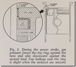
The top ring and its upper and lower lands wear fastest for several reasons: The ring and land wearing surfaces are exposed to the hot, high pressure gases of combustion and therefore lubri cation is imperfect. The outer face of the top ring is forced hard against the cylinder bore by the high pressure gases getting behind the ring, Fig. 3.
PISTON SLAP
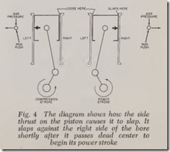
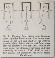
On the compression stroke, Fig. 4, the compres sion pressure pushes downward on the piston while the rod resists this pressure by pushing upward on the piston pin. The combined action of these two forces pushes ( thrusts) the piston against the left side of the bore-because the rod slopes upward to the left.
During the power stroke, the rod slopes upward to the right. Combustion pressure pushes down ward on the piston and the rod r esists this pres sure by pushing upward on the piston pin. The combination of these two forces thrusts the piston against the right side of the bore .
The direction of side thrust acting on the piston changes from left to right when the piston passes top dead center. This change in direction of thrust pulls the piston away from the left side of the bore and slaps it against the right side. If the clearance between piston and bore is too large a noise is heard which is called piston slap.
When the pistons and bores are unworn no piston slap will be heard when the engine is warm because the clearance is small. If the engine has aluminum pistons, slight slap may be h eard when a cold engine is first started. However, thes epistons quickly warm up and expand, reducing the clearance and eliminating the noise.
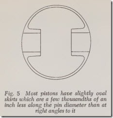
Modern pistons, instead of bein g ground per fectly circular are ground slightly oval (cam ground) being about .009″ less in diameter across the piston pin hole than at right angles to the pin hole, Fig. 5.
Usually, aluminum skirts are ground about half a thousandth larger in diam eter at the bottom of the skirt. In other words the skirt flares or tapers outward by .0005″.
However, after thousands of miles of service, the thrust forces acting on the skirt gradually reduce its diam eter so th at the skirt now tapers inward instead of outward. The skirt is said to have collapsed. This reduction in diameter is in addition to any surface wear of the skirt. The collapse increas es the clearance between bore and skirt and results in more piston slap.
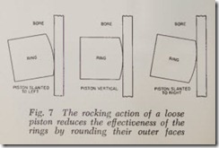
Piston slap may be thou ght of as a rocking action of the piston in th e bore as shown in Fig. 6. As bore wear and skirt collapse increase, the rocking action increas es. The rocking of the piston rounds off th e outer faces of the rings and reduces their effectiveness, Fig. 7. Gas pressure leaks downward past thes e round ed surfaces and oil leaks upward into th e combustion chamber and so oil consumption is increased.
SEATING RINGS
When new rings are inst alled they must seat themselves into the bor e. To do this the bore must be slightly rough, so th at in the first few hundred miles, rings and bores wear in together-or seat. If th e rings do not seat, oil consumption will be high and in addition ring wear may be rapid becaus e of excessive blow-by .
Th erefore when rings are to be installed in worn bores, if there is a hard glaze on the bore surface, the glaze should be removed with a glaze buster or a spring-loaded hone. 1 The glaze appears to be caused by the deposit of a film of varnish or lacquer formed from some of the ingredients of fuel or oil.
EXCESSIVE OIL CONSUMPTION
There are only two ways in which an abnormal amount of oil can leave the crankcase of an engine: through external leaks, and by getting into the combustion chambers where it is burned.
OIL LOSS BY LEAKAGE
External leaks may be classified as occurring under three different conditions:
1. When the pressure in the crankcase is nor mal, oil may be leaking from the engine past some gasket or through some loose metal-to-metal joint that is in direct contact with the oil in the oil pan.
2. When the crankcase pr essure is above nor mal because of an excessive amount of blow-by or because the outlet and inlet of the crankcase ventilating system are partially or completely clogged, oil may be forced out of the crankcase through the front or rear bearings. When the crankcase pressure is too high, the underside of the engine generally has the appearance of leaking at every joint.
3. Sometimes the crankcase pressure is below normal because the ventilator outlet or the splash pan around it has become bent in such a way that the velocity of the air passing under the car at high speeds produces enough vacuum at the lower end of the ventilator outlet to suck enough oil vapor out of the crankcase to result in excessive oil consumption.
OIL LOSS INTO COMBUSTION CHAMBER
Oil can pass from the crankcase into the com bustion chambers in only three ways:
1. Through a broken or porous vacuum dia phragm on the vacuum side of combination fuel pumps.
2. Through worn intake and exhaust valve guides on overhead valve engines and through worn intake valve guides on L-head engines.
3. Past the piston rings.
