Solid-State Timer Relays
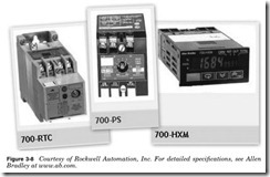
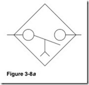
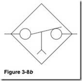
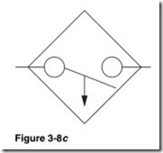
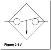
The solid-state timers in Fig. 3-8 can have standard electromechanical coils or solid-state coils. Solid-state timers use a potentiometer to set or adjust the timing cycle. The potentiometer can be internal or external.
Care should be taken not to apply voltage to the potentiometer circuit, as this will damage the timer. Timers with solid-state inputs typically use a Normally Open contact to initiate the timing cycle. Care should be taken not to apply voltage to the initiating circuit, as this will damage the timer. Solid-state timers must have power applied to operate the timer. If the power fails, the timing cycle will terminate. Length of the timing cycle can be from a fraction of a second to hours.
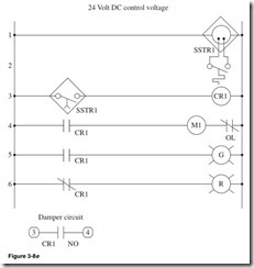
Figure 3-8e illustrates how to amplify the solid-state timer relay to control many circuits.
Line 1 Supply continuous power to solid-state timer relay SSTR1.
Line 2 Temperature switch closes at a preset temperature and trig- gers SSTR1.
Line 3 Normally Open time-close contact of solid-state relay SSTR1 and control relay CR1. When SSTR1 is triggered, preset time cycle starts; when complete contact is closed, CR1 will be energized.
Line 4 Normally Open contact of CR1, motor starter M1, and Normally Closed overload contact of M1. When CR1 is energized, the contact will close and the start M1 will be energized, starting the blower motor.
Line 5 Normally Open contact of CR1, green pilot light. When CR1 is energized, the green pilot light will be illuminated.
Line 6 Normally Closed contact of CR1, red pilot light. When CR1 is energized, the contact CR1 will open and the red pilot light will be off.
Output Normally Open contact of CR1. When CR1 is energized, the contact will close, completing the damper circuit.
Shunt Trip Breaker
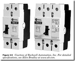
A shunt trip breaker such as those in Fig. 3-9 has an electromechanical relay that allows the breaker to be tripped remotely by a low-voltage con- trol circuit. The coil can be any voltage offered by the manufacturer and is usually in the range of 12 to 600 V AC/DC. The shunt trip relay allows systems such as the fire alarm or emergency power off (EPO) system to trip the circuit breaker in case of an alarm event. It is important that the shunt breaker be connected and tested. NEC Section 645.10 states that an IT equipment room must have remote disconnect of all power in the room.
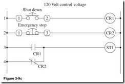
In Fig. 3-9c there are two ways to trip the shunt trip: Normally Open circuit and Normally Closed circuit.
Shown in Fig. 3-9c:
Line 1 Terminal 1, Normally Open Mushroom push button, ter- minal 2, and control relay CR1. When the Shutdown push button is pressed, CR1 is energized.
Line 2 Terminal 1, Normally Closed Mushroom push button, ter- minal 3, and control relay CR2. When the Shutdown push button is pressed, CR2 is deenergized.
Line 3 Normally Open contact of CR1 and shunt trip coil ST1. When CR1 is energized, the CR1 contact will close and the breaker will trip.
Line 4 Normally Closed contact of CR2. When CR2 is deenergized, the CR2 contact will close and the breaker will trip.
Three-Phase Motor Starter
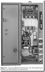
Motor starters such as that in Fig. 3-10 are electromechanical relays that allow the control of high voltage and current with the line or low- voltage control circuit.
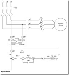
In the motor starter circuit in Fig. 3-10a, L1, L2, and L3 are connected to a circuit breaker to protect the circuit. The control transformer is used to reduce the line voltage to a 120-V control circuit. The control trans- former is connected to line 1 and line 2. The control circuit is protected but fuses FU. The fuses are connected to the transformer terminal H1 and H4. The X1 terminal of the control transformer is connected to fuse FU to protect the control circuit devices and wires. L1 is the high, or hot, line of the control circuit. The X2 terminal is grounded and is the neutral side of the control circuit.
Shown in Fig. 3-10a:
Line 1 Terminal 1, Normally Closed Stop push button, terminal 2. Down one line, Normally Open contact of motor starter coil M1. Up one line, Normally Open Start push button, terminal 3, motor starter coil M1, and the Normally Closed overload contacts of M1. When the Start button is pushed, the M1 coil is energized, the M1 contacts close, and the motor starts. The M1 contact closes and electrically latches the circuit. The motor will continue to run until the Stop push button is pressed or power to the control circuit is shut off.
