DATA TRANSMISSION BASICS
All digital electric or electromagnetic information must be transmitted by means of at least a trans- mission channel, which is a pathway for conveying the information. It may be defined by an electrical wire that connects devices, or by a radio, laser, or other wireless energy source that has no obvious physical presence. Information sent through a transmission channel has a source from which the information originates, and a destination to which it is delivered. Although originating from a single source, there may be more than one destination, depending upon how many receiving stations are linked to the channel and how much energy the transmitted signal possesses.
A digital message is represented by an individual data bit, which is one digit in the binary numbering system, either 0 or 1. In data transmission, bits can be encapsulated into multiple-bit message units. A byte, which consists of eight bits, is an example of a message unit that may be conveyed through a digital transmission channel. A collection of bytes may itself be grouped into a form of message or other higher-level message unit, such as character, word, or page.
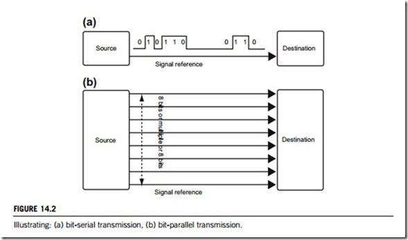
In practice, most digital messages are vastly longer than just a few bits, and therefore the whole cannot be transmitted instantaneously. There are two ways to transmit the bits that make up a data message: serial or parallel. Serial transmission sends bits sequentially, one bit at a time, over a single channel. In parallel transmission, bits of a data message are transmitted simultaneously over a number of channels, which are generally organized in multiples of a byte. Figure 14.2 is an illustration of bit- serial and bit-parallel transmissions, respectively.
Serialized data are not generally sent at a uniform rate through a channel. Instead, there is usually a burst of regularly spaced binary bits followed by a pause, after which the data flow resumes. Packets of binary data are sent in this manner, possibly with variable-length pauses between packets, until
message has been fully transmitted. In order for the receiving end to know the proper moment to read individual binary bits from the channel, it must know exactly when a packet begins and how much time elapses between bits. Two basic techniques, synchronous and asynchronous techniques, are employed to ensure correct serial data transmission.
(1) In synchronous systems, separate channels are used to transmit data and timing information. The timing channel transmits clock pulses to the receiver. Upon receipt of a clock pulse, the receiver reads the data channel and latches the bit value found on the channel at that moment. The data channel is not read again until the next clock pulse arrives. Because the transmitter originates both the data and the timing pulses, the receiver will read the data channel only when told to do so by the transmitter (via the clock pulse), and thus synchronization is guaranteed.
(2) In asynchronous systems, a separate timing channel is not used. The transmitter and receiver must be preset in advance to an agreed-upon baud rate. The baud rate refers to the rate at which data are sent through a channel, and is measured in electrical transitions per second (at bits per second: bps). A very accurate local oscillator within the receiver will then generate an internal clock signal that is equal to the transmitters within a fraction of a percent. For the most common serial protocols, data are sent in small packets of 10 or 11 bits, eight of which constitute message information, while the others are used for checking. When the channel is idle, the signal voltage corresponds to a continuous logical “1”. A data packet always begins with a logical “0” (the start bit) to signal to the receiver that a transmission is starting. This triggers an internal timer in the receiver which generates the necessary clock pulses. Following the start bit, eight bits of message data are sent bit by bit at the agreed baud rate. The message is concluded with a parity bit and a stop bit.
Two codeword standards are used for both bit-serial and bit-parallel transmissions. Extended Binary Coded Decimal Interchange Code (EBCDIC) Standard is a binary coding scheme developed by IBM Corporation for the operating systems within its larger computers. EBCDIC is a method of assigning binary number values to characters (alphabetic, numeric, and special characters such as punctuation and control characters).
American Standard Code for Information Interchange (ASCII) Standard is a single-byte encoding system (i.e., uses one byte to represent each character), and using the first seven bits allows it to represent a maximum of 128 characters. ASCII is based on the characters used to write the English language (including both upper and lower-case letters). Extended versions (which utilize the eighth bit to provide a maximum of 256 characters) have been developed for use with other character sets.
Both electrical noise and disturbances may cause data to be changed as they pass through a transmission channel. If the receiver fails to detect this, the received message will be incorrect, possibly resulting in serious consequences. A parity bit is added to a data message for the purpose of error detection. In the even-parity convention, the value of the parity bit is chosen so that the total number of “1” digits in the combined data plus the parity packet is an even number. Upon receipt of the message, the parity needed for the data is recomputed by local hardware and compared to that received with the data. If any bit has changed state, the two will not match, and an error will have been detected. In fact, if an odd number of bits (not just one) have been altered, the parity will not match, but if an even number of bits have been reversed, the parity will match even though an error has occurred. However, a statistical analysis of data transmission errors has shown that a single-bit error is much more probable than a multiple-bit error in the presence of random noise, so parity is a reliable method of error detection.
Another approach to error detection involves the computation of a checksum. In this case, the packets that constitute a message are added arithmetically, and checksum number is appended to the packet sequence, calculated such that the sum of data digits plus the checksum is zero. When received, the packet sequence may be added, along with the checksum, by a local microprocessor. If the sum is not zero, an error has occurred. As long as the sum is zero, it is highly unlikely (but not impossible) that any data have been corrupted during transmission.
Data compression (and decompression) is often used to minimize the amount of data to be transmitted or stored. As with any transmission, compressed data transmission only works when both the sender and receiver of the message understand and execute the same encoding (and decoding) scheme. Two algorithms, lossless and lossy, are used for compression and decompression. Many encoding (and decoding) schemes, such as the well-known Huffman and Manchester methods, have been developed in the past decades.
Huffman coding is an entropy encoding and decoding algorithm used for lossless data compression and decompression. The term refers to the use of a variable-length code table for encoding a source symbol (such as a character in a file) where the variable-length code table has been derived in a particular way based on the estimated probability of occurrence for each possible value of the source symbol.
Manchester coding is a line code in which the encoding of each data bit has at least one transition and occupies the same time. Manchester coding offers more complex codes, e.g. 8B/10B encoding, which use less bandwidth to achieve the same data rate (but which may be less tolerant of frequency errors and jitter in the transmitter and receiver reference clocks).
Compression is useful because it helps reduce the consumption of expensive resources, such as hard-disk space or transmission bandwidth. Large volumes of data need to be stored nowadays and massive amounts are carried over transmission links. Compressing data reduces storage and trans- mission costs, but compressed data must be decompressed to be used, which may be detrimental to some applications.
The encoding and decoding algorithms developed for data compression have been extended to data communication security. This topic, data communication security, is beyond the coverage of this book. Readers who are interested in it please refer to the relevant literature for further studies.
14.1.1 Data transmission over different distances
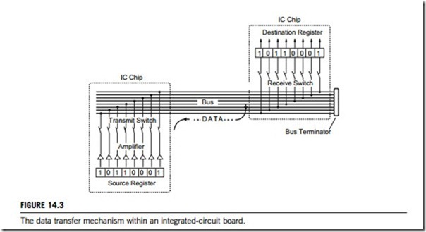
Data are typically grouped into packets that are 8, 16, 32, 64, 128 or 256 bits long, and passed between temporary holding units called registers that can be parts of a memory or an input/output (I/O) port of an integrated circuit (IC) chip or chipset. Data within a register are available in parallel because each bit exits the register on a separate conductor. To transfer data from one register to another, the output conductors of one register are switched onto a channel of parallel wires referred to as a bus. The input conductors of another register, which is also connected to the bus, capture the transferred data. Following a data transaction, the content of the source register is reproduced in the destination register. It is important to note that after any digital data transfer, the source and destination registers are equal; the source register is not erased when the data are sent. Bus signals that exit central processing unit (CPU) chips and other circuitry are electrically capable of traversing about one foot of a conductor on an integrated circuit board, or less if many devices are connected to it. Special buffer circuits may be added to boost the bus signals enough for transmission over several additional centimeters of conductor length, or for distribution to many other chips.
Both transmit and receive switches, as shown in Figure 14.3, are electronic, and operate in response to commands from a CPU. It is possible that two or more destination registers will be switched on to receive data from a single source, but only one source may transmit data onto the bus at any given time. If multiple sources were to attempt transmission simultaneously, an electrical conflict would occur when bits of opposite value are driven onto a single bus conductor. Such a condition is referred to as a bus contention. Not only will a bus contention result in the loss of information, but it also may damage the electronic circuitry. As long as all registers in a system are linked to one central control unit, bus contentions should never occur if the circuit has been designed properly.
When the source and destination registers are part of an integrated circuit (within a CPU chip, for example), they are extremely close (within some thousandths of an inch). Consequently, the bus signals are at very low power levels, may traverse a distance in very little time, and are not very susceptible to external noise and distortion. This is the ideal environment for digital transmissions. However, it is not yet possible to integrate all the necessary circuitry for a computer (i.e., CPU, memory, peripherals such as disk control, video and display drivers, etc.) on a single chip. When data are sent off-chip to another integrated circuit, the bus signals must be amplified by the conductors extended out of the chip as external pins. Amplifiers may be added to the source register, as shown in Figure 14.3.
Data transferring between a CPU and its peripheral chips generally need mechanisms that cannot be situated within the chip itself. A simple technique to tackle this might be by extending the internal
buses with a cable to reach the peripheral. However, this would expose all bus transactions to external noise and distortion. When transmission with the peripheral is necessary, data are first deposited in the holding register by the CPU. These data will then be reformatted, sent with error-detecting codes, and transmitted at a relatively slow rate by digital hardware in the bus interface circuit. Data sent in this manner may be transmitted in byte-serial format if the cable has eight parallel channels, or in bit-serial format if only a single channel is available.
When relatively long distances are involved in reaching a peripheral device, driver circuits are required after the bus interface unit to compensate for the electrical effects of long cables.
However, if many peripherals are connected, or if other IC chips are to be linked, a local area network (LAN) is required, and it becomes necessary to drastically change both the electrical drivers and the protocol to send messages through the cable. Because multiple cables are expensive, bit-serial transmission is almost always used when the distance exceeds about 10 meters.
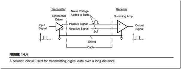
In either a simple extension cable or a LAN, a balanced electrical system is used for transmitting digital data through the channel. The basic idea is that a digital signal is sent on two wires simulta- neously, one wire expressing a positive voltage image of the signal and the other a negative one. Figure 14.4 illustrates the working principle. When both wires reach the destination, the signals are subtracted by a summing amplifier, producing a signal swing of twice the value found on either incoming line. If the cable is exposed to radiated electrical noise, a small voltage of the same polarity is added to both wires in the cable. When the signals are subtracted, the noise cancels and the signal emerges from the cable without noise.
A great deal of technology has been developed for LAN systems to minimize the amount of cable required and maximize the throughput. Costs have been concentrated in the electrical-interface card
that is to drive the cable, and in the transmission software, not in the cable itself. Thus, the cost and complexity of a LAN are not particularly affected by the distance between stations.
14.1.2 Electric and electromagnetic signal transmission modes
Most modes of transmitting electrical and electromagnetic signals show up in most data transmission devices. Full-duplex, for example, might not give the best performance when most data are moving in one direction; often the case for data transmission, so some full-duplex equipment has the option of being operated in a half-duplex mode for optimal transmission.
(1) Simplex transmission mode
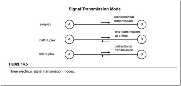
Simplex transmission is a mode in which data only flow in one direction, as illustrated at the top of Figure 14.5. It is used for certain point-of-sends terminals in which send data are entered without needing a corresponding reply. Radio or TV is an example of simplex transmission.
(2) Half-duplex transmission mode
Half-duplex transmission is a two-way flow of data between computer terminals. Data travel in two directions, but not simultaneously only one direction can be active at a time. This mode is commonly used for linking computers together over telephone lines, as is illustrated in the middle section of Figure 14.5.
(3) Full-duplex transmission mode
The fastest directional mode of transmission is full-duplex transmission. Here, data are transmitted in both directions simultaneously on the same channel, so it can be thought of as similar to automobile traffic on a two-lane road. It is made possible by devices called multiplexers, and is primarily limited to mainframe computers because of the expensive hardware required. This case is illustrated in the bottom section of Figure 14.5.
(4) Multiplexing transmission modes
Multiplexing is sending multiple signals or streams of information on a carrier at the same time in the form of a single, complex signal, and then recovering the separate signals at the receiving end. In analog transmission, signals are commonly multiplexed using frequency-division multiplexing (FDM), in which the carrier bandwidth is divided into subchannels of different frequency widths, each carrying a signal at the same time in parallel. In digital transmission, signals are commonly multi- plexed using time-division multiplexing (TDM), in which the multiple signals are carried over the same channel in alternating time slots. In some optical-fiber networks, multiple signals are carried together as separate wavelengths of light in a multiplexed signal using dense wavelength division multiplexing (DWDM).
Frequency-division multiplexing (FDM) is a scheme in which numerous signals are combined for transmission on a single transmission line or channel. Each signal is assigned a different frequency (subchannel) within the main channel. When FDM is used in a transmission network, each input signal is sent and received at maximum speed at all times, but if many signals must be sent along a single long-distance line, the necessary bandwidth is large, and careful engineering is required to ensure that the system will perform properly.
Time-division multiplexing (TDM) is a method of putting multiple data streams in a single signal by separating the signal into many segments, each having a very short duration. Each individual data stream is reassembled at the receiving end based on timing.
Dense wavelength division multiplexing (DWDM) is a technology that puts data from different sources together on an optical fiber, with each signal being carried at the same time, at its own separate wavelength. Using DWDM, up to 80 (and theoretically more) separate wavelengths or channels of data can be multiplexed into a light stream transmitted on a single optical fiber. Each channel carries a time division multiplexed (TDM) signal. In a system with each channel carrying 2.5 Gbps (billion bits per second), up to 200 billion bits can be delivered a second by the optical fiber. DWDM is also sometimes called wave division multiplexing (WDM).
Since each channel is demultiplexed at the end of the transmission to retrieve the original source, different data formats can be transmitted together. Specifically, Internet Protocol (IP) data, Synchronous Optical Network data (SONET), and asynchronous transfer mode (ATM) data can all travel at the same time within the optical fiber. DWDM promises to solve the “fiber exhaust” problem and is expected to be the central technology in the all-optical networks of the future.


