Timing Relays
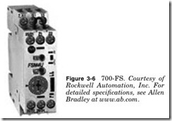
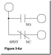
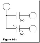
Timing relays are available in many configurations. They can have pneumatic or solid-state timers. Pneumatic timers will continue to oper- ate when the power is lost. Timers can have instantaneous contacts. Instantaneous contacts are operated directly by the relay coil and are not time-controlled. This combines the function of a standard relay and a timer relay. Solid-state timers are more accurate and have a greater range of control times. Timing relays can be time off delay (time delay starts when the relay is deenergized) or time on delay (time delay starts when the relay is energized). The relay shown in Fig. 3-6 allows both configurations. It has single-pole double-throw with one Normally Open contact and one Normally Closed contact (SPDT), Normally Open con- tact NO. See Fig. 3-6a to d.
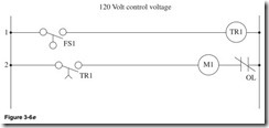
Shown in Fig. 3-6e:
Line 1 Float switch FS1, timer relay TR1. When the level reaches a preset amount, the float switch closes and starts the time cycle.
Line 2 Normally Open time-close contact, pump motor starter M1, Normally Closed overload. When the TR1 is energized, it starts the time preset cycle; when the time cycle is complete, the contact TR1 will close, the motor starter will be energized, and the pump will start. This allows the level to fluctuate without the pump running intermittently.
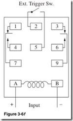
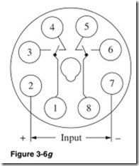
Figure 3-6f is the pin out for the 700-HS, and Fig. 3-6g is the pin out for the 700-HV; both are ice cube–style timer relays. These can change from manufacturer to manufacturer. The pin outs are usually printed on the relay. The pin out should be read before connecting the timer.
Solid-State Relays
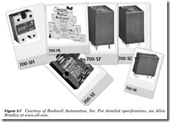
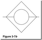
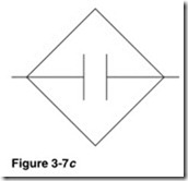
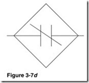
The solid-state relays shown in Fig. 3-7 have several advantages over standard relays. Solid-state relays have no moving parts and are imper- vious to shock and vibrations. They are sealed from moisture and dirt.
The major advantage of solid-state relays is that the input and output circuits are completely isolated. This prevents spikes and noise in the control circuit from being transmitted to the controlled circuit. Solid- state relays can be used to control AC or DC circuits.
The solid-state relay typically uses a reed relay or photoelectric device to isolate the circuits. The reed relay is operated by an electromagnetic coil to close a sealed reed contact. In a photoelectric isolated solid-state relay, an LED is used to operate a photosensitive switch in an AC circuit; this would be a TRIAC. In a DC circuit it would be a transistor.
Solid-state relays are controlled by low voltage and current. This allows for the use of smaller conductors.
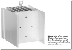
Solid-state relays are sensitive to heat and generate a lot of heat. They should be mounted on a heat sink as shown in Fig. 3-7e and should have good ventilation.
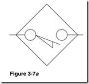
Solid-state relays typically have one Normally Open contact (SPST) or one Normally Open and one Normally Closed contact (SPDT) (reed- type only).
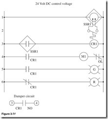
Figure 3-7f illustrates how to amplify the solid-state relay to control many circuits.
Line 1 Supply continuous power to solid-state relay SSR1.
Line 2 Temperature switch closes at a preset temperature and trig- gers SSR1.
Line 3 Normally Open contact of solid-state relay SSR1 and control relay CR1. When SSR1 is triggered closed, CR1 will be energized.
Line 4 Normally Open contact of CR1, motor starter M1, and Normally Closed overload contact of M1. When CR1 is energized, the contact will close and the starter M1 will be energized, starting the blower motor.
Line 5 Normally Open contact of CR1, green pilot light. When CR1 is energized, the green pilot light will be illuminated.
Line 6 Normally Closed contact of CR1, red pilot light. When CR1 is energized, the contact CR1 will open and the red pilot light will be off.
Output Normally Open contact of CR1. When CR1 is energized, the contact will close, completing the damper circuit
