From (4.20) the speed of the mmf fundamental dx/dt is
dxdt ν=1 = 2τf1 (4.37)
The corresponding angular speed is
Ω =1 dxdt D2 = 2pπ1f1 ; n1 = pf11 (4.38)
The mmf fundamental wave travels at a speed n1 = f1/p1. This is the ideal speed of the motor with a cage rotor.
Changing the speed may be accomplished either by changing the frequency (through a static power converter) or by changing the number of poles.
Changing the number of poles to produce a two-speed motor is a traditional method. Its appeal is still strong today due to low hardware costs where continuous speed variation is not required. In any case, the rotor should have a squirrel cage to accommodate both pole pitches. Even in variable speed drives with variable frequency static converters, when a very large constant power speed range (over 2(3) to 1) is required, such a solution should be considered to avoid a notable increase in motor weight (and cost).
Two – speed induction generators are also used for wind energy conversion to allow a notable speed variation to extract more energy from the wind speed.
There are two possibilities to produce a two-speed motor. The most obvious one is to place two distinct windings in the slots. The number of poles would be 2p1> 2p2. However the machine becomes very large and costly, while for the winding placed on the bottom of the slots the slot leakage inductance will be very large with all due consequences.
Using a pole-changing winding seems thus a more practical solution. However standard pole-changing windings have been produced mainly for 2p1/2p2 = 1/2 or 2p1/2p2 = 1/3.
The most acclaimed winding has been invented by Dahlander and bears his name.
In essence the current direction (polarity) in half of a 2p2 pole winding is changed to produce only 2p1 = 2p2/2 poles. The two-phase halves may be reconnected in series or parallel and Y or ∆ connections of phases is applied. Thus, for a given line voltage and frequency supply, with various such connections, constant power or constant torque or a certain ratio of powers for the two speeds may be obtained.
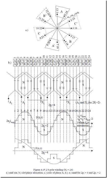
Let us now proceed with an example and consider a two-layer three-phase winding with q = 2, 2p2 = 4, m = 3, Ns = 24slots, y/τ = 5/6 and investigate the connection changes to switch it to a two pole (2p1 = 2) machine.
The design of such a winding is shown on Figure 4.15. The variables are t = g.c.d(Ns, p2) = 2 = p2, αes = αet = 2πp2/Ns = π/6, and Ns/t = 12. The star of slot emf phasors is shown in Figure 5.15a.
Figure 4.15c illustrates the fact that only the current direction in the section A2 -–X2 of phase A is changed to produce a 2p1 = 2 pole winding. A similar operation is done for phases B and C.
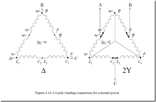
A possible connection of phase halves called ∆/2Y is shown in Figure 4.16. It may be demonstrated that for the ∆ (2p2 = 4)/2Y (2p1 = 2) connection, the power obtained for the two speeds is about the same.
We also should notice that with chorded coils for 2p2 = 4 (y/τ = 5/6), the mmf distribution for 2p1 = 2 has a rather small fundamental and is rich in harmonics.
In order to achieve about the same winding factor for both pole numbers, the coil span should be greater than the pole pitch for the large number of poles (y = 7, 8 slot pitches in our case). Even if close to each other, the two winding factors are, in general, below 0.85.
The machine is thus larger than usual for the same power and care must be exercised to maintain the acceptable noise level.
Various connections of phases may produce designs with constant torque (same rated torque for both speeds) or variable torque. For example, a Y – YY parallel connection for 2p2/2p1 = 2/1 is producing a ratio of power P2/P1 = 0.35 – 0.4 as needed for fan driving. Also, in general, when switching the pole number we may need modify the phase sequence to keep the same direction of rotation.
One may check if this operation is necessary by representing the stator mmf for the two cases at two instants in time. If the positive maximum of the mmfs advances in time in opposite directions, then the phase sequence has to be changed.

