Typical Motor Control Installation
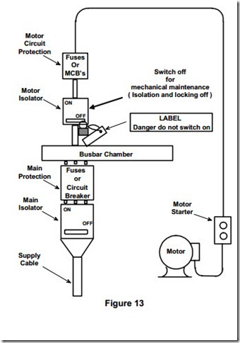
Figure 13 illustrates a typical layout where the isolator is remote from the motor
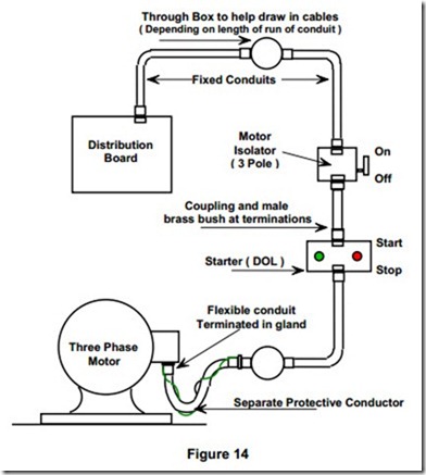
Figure 14 illustrates an example of a motor final circuit equipment layout.
Note: A separate earth protective conductor was fitted on the outside of the older types of flexible conduit. Therefore mechanical protection was not provided.
In modern installations it must be installed inside the flexible conduit with the power cables.
Flexible Conduit
Flexible conduit is made of interlinked metal spirals often covered with a PVC sleeving. The tubing must not be relied upon to provide a continuous earth path and, consequently, a separate protective conductor must be run inside the flexible tube.
Flexible conduit is used for the final connection to motors so that the vibrations of the motor / machine are not transmitted throughout the electrical installation. It also allows adjustments to be made to the final motor position for drive belt tension etc.
Assembly Instruction
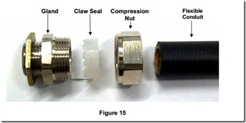
Figure 15 shows one type of flexible conduit and gland.
1. Cut the conduit square with a knife edge blade rather than a hacksaw.
2. Dismantle the gland body.
3. Fix the gland body in the enclosure entry.
4. Assemble the compression nut and claw seal loosely on the conduit end ( correct way round ).
5. Push the conduit down into the gland body.
6. Assemble the compression nut onto the body thread while continuing to apply a force on the conduit.
7. Tighten the compression nut until finger tight.
8. Using a spanner tighten the compression nut two further turns to provide a dust and water tight seal between the conduit and gland.


