Tackling the problem or reducing motor noise
A continuing program at E. I. du Pont has signifi cantly reduced worker ex posure to potenti ally harmful noise levels gen erated by totally en closed, fan-cooled induc tion motors.
By TERRENCE A. DEAR, F.I.O.A.
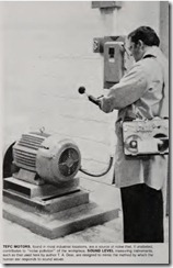
MOTORS are everywhere in industry, and so is the noise they make. Because the motor noise com bines with the noise of the driven equipment, motors are often at the center of a cluster of problem-noise sources. For more than 20 years, the Du Pont Company has been concerned with reducing this noise.
In the mid-1950s, silencers were designed and fabricated for 75-hp, totally enclosed, fan-cooled (TEFC) motors located at one of its plant sites. A few years ·later, commercial motor silencers became available and were applied to TEFC motors ranging from 50 to 125 hp. However, such silencers are bulky and expensive as retrofit hardware, so Du Pont engineers attacked the origins of motor noise. It was found that by improved motor cooling-fan design, significant and uniform reductions in noise levels could be achieved. To understand why these design features do reduce motor noise, it’s useful to review briefly how vibration of material and air in equipment becomes noise heard by the ear.
Sound and noise
Vibratory motion of a sounding body reaches the ear by means of “molecular” waves in the intervening medium ; sound will not travel in a vacu um. The velocity of sound in air at OoC is about
1090 ft/sec. A change in the tempera ture changes the speed of sound at the rate of approximatel y 2 ftlsec/°C increased temperature increases speed. Velocity of sound in denser media (such as water) is generally much high er than in air and is not so dependent upon temperature.
Because a sound wave is actually transmitted by the vibration of mole cules of media in which it is traveling, it can eventually exert oscillatory pres sure on the eardrum of a listener in range. As the molecules react in the direction of incidence of the wave, the pressure forces the eardrum inwards. Rarification of the medium (usually air) brought about by the reversing molecular motion causes the eardrum to respond in the opposite direction. Thus, the eardrum vibrates at the sig nal frequency (or frequencies ) of the sound wave. The internal mechanism of the ear converts the vibration of the eardrum to electrical impulses in the brain and the sound is “heard.”
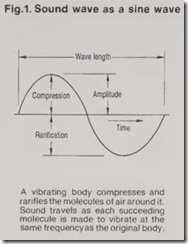
Sound waves are often represented by sine waves (Fig. 1). Peaks represent compression of the air molecules; troughs indicate rarification as the vibrating source moves in the opposite direction from the initial sound wave. The wave length of the sound wave is the distance between two repeating points on the wave, and the amplitude is the magnitude of the sound pressure above or below the local barometric value. The rms (effective) value of amplitude is used in describing steady state sound pressure. Frequency of the wave is found by dividing the velocity by the wave length.
The amplitude of a sound wave determines the loudness of sound and the energy in the wave . Frequency and pitch are analogous terms-the higher the frequency, the higher the pitch .
A musical tone is made up of regularly repeating or periodic vibrations. The sound of the plucked, vibrating string on a guitar, for example, is amplified by a properly tuned wooden case. But noise, defined as “unwanted sound,” is generally associated with irregular vibrations. Sounds reaching the ear in most industrial locations do not consist of pure tones. They are a mix of sounds from sounding bodies and/or interfaces, reflected sound, transmitted sound, and sound from items that are in sympathetic vibration with other sources. For instance, the surface of a motor that is vibrating will cause noise. The cooling fan causes turbulence in the surrounding air and also generates noise. If the motor is located near a poorly braced plywood wall, the sound waves will cause the plywood to vibrate at the same fre quencies, and because it has a greater surface area than the motor, it can greatly amplify the sound level. Such sounds are clearly “noise.”
Adverse effects of noise
Noise can annoy those exposed to it, and there is potential physical damage associated with it. Binaural deteriora tion of hearing that cannot be explained by the normal aging process or disease is often due to long-term exposure to excessive noise. It is not unusual for audiometric tests to show that some 25-year-old employees who spend hour s at discos or riding motor cycles come on the job with 40-year-old ears.
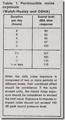
In 1969, the federal government per ceived noise exposure to be of sufficient importance to justify specific coverage under the Walsh-Healey Act. At that time, a noise exposure limit was imposed. Limits were placed on the number of hours an employee could work in a noisy location, the number of hour s depending on the sound level (see Table 1). This was later reinforced by making these exposure levels part of OSHA regulations in 1971, thus extending coverage to all employees of a business engaged in or affecting interstate or foreign commerce.
Measuring sound
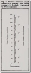
Reducing noise from motors, or from any other source, begins with measur ing levels and identifying contributors. Sound pressure is measured in units of “micropa scals.” The minimum sound pressure that the young human ear can detect is about 20 micropascals at 1000 cycles/sec. But the listener’s ear does not respond to an increase in sound pressure in a linear fashion. Twice the sound pressure is not detected as a sou nd that is twice as loud. The response is logarithmic. A decibel scale expresses the logarithm of the ratio of a measured quantity to a reference quantity. Thus, this scale has been adapted to the measurement of sound. The level of sound above the reference level-the threshold of hearing, 20 micropascals-i s expressed in decibels (dB). Fig. 2 shows a typical decibel scale.
Sound-level measuring instruments generally consist of a microphone to pick up and convert the sound pressure to electrical impulses, signal processing electronics, and a ballistic meter cali brated in decibels. They thus mimic, in most ways, the manner in which the human ear detects sound.
There is one additional complicating factor: the ear is not equally sensitive to sound at all frequencies. For this reason, even though the sound-pres sure level of two different noises may be the same, one may be considered louder than the other if one is concen trated in the frequency region to which the ear is more sensitive. To allow for this, sound-level meters have several frequency-weighting networks that al ter the sensitivity of the meter with respect to the frequency. The most commonly used one is called the “A weighting” network. This network is specified by OSHA regulations for sound-level measurements, and mea surements taken using this A scale are expressed in dB(A) or simply dBA.
There is a natural time delay in the ear’s response to sound. Rapid fluctua tions are thus “time-averaged.” To approximate even more closely the response of the human ear to sound, two response times are built into the meters. There are “fast” and “slow” responses. The first has a time con stant of 1/s sec and the other 1 sec. OSHA specifies the “slow” response for sound-level measurements.
Enclosures and damping
Early attempts at motor noise abate ment were based upon a generally accepted rule-of-thumb setting the maximum allowable human noise exposure level at 97.5 dBA. To allow for noise contributions from other sources and for reflection, individual sources were permitted to generate noise levels no greater than 91.5 dBA. To meet this requirement, it was often necessary to provide sound treatment after the motor was installed, sometimes called retrofit. Typically, a 250-hp, 3600-rpm TEFC motor was provided with a cov ering structure (enclosure) made up of angle iron, 18-gauge sheet steel, and a l-in fiberglass lining. Inlet sound absorbing ducts were provided for cool ing air and exhaust air. Another meth od of quieting units is the isolation and damping of vibration using material or hardware to prevent transmission of sound through floor slabs, etc.
Reducing noise at source
Du Pont’s noise program focuses on control of noise at the source as a long-range approach to achieving last ing benefits. Origins of noise in motors are usually points where local pressure perturbations are caused by air turbu lence and forced motion of component surfaces. By reducing the noise level at the source through proper design modi fications, additional benefits can be gained: vibration will be reduced,equipment life extended, and mainte nance reduced.
Noise from TEFC motors has its primary origins along the surfaces of the motor cooling fan as it cuts through the air. As might be expected, the highest noise generation is along the tips of the blades, where the rela tive velocity and air turbulence are at a maximum. Attacking this origin of motor noise by engineering design showed that there were numerous modifications that could be effective slower tip speed, improved inflow paths, improved motor insulations, and changes in fan blades and housing structures.
A review of one case history points out other approaches that can be taken in dealing with motor noise through design. Initial tests on two large induc tion motors showed sound levels in the high 90-dBA range. Because of other noise contributions expected in the work area in which they were to be installed, they had been specified to be in the low 80-dBA range.
Thorough investigation pointed to three major noise contributors. One proved to be a force wave at twice the line frequency causing the stator to deform in a near-sinusoidal mode around the periphery of the core. This set up vibration-induced resonances in the rotor and stator cores that were efficiently coupled to the motor struc ture. In addition, components directly in contact with the surrounding air contributed to radiated noise by gener ating turbulence. A second high-fre quency noise was due to air-gap flux harmonics caused by pole pairs differing by a relatively small integer.
Of primary importance in this instance was a third noise generated by harmonic waves produced by the inter action of rotor and stator slots. The actual analysis of these waves is quite complex, but it is sufficient to say that the interaction between them and the main air-gap waves produced forces with identifiable frequencies and num ber of nodes. Increasing the number of rotor bars was the solution in this case. Changing the number of rotor bars for all induction motors will not necessari ly provide the same results; in fact, this approach could intensify the problem in some cases. Each case must be con sidered on an individual basis. In the example cited, redesign was accom plished by the manufacturer. The noise level of these large, high-horsepower motors dropped below 80 dBA with corresponding reductions in core vibra tion levels to lfso of the original accelerations. ‘
Specifying low-noise motors
Specifying low-noise motors is be coming more common. A vendor can be expected to meet noise specifications as well as any other motor performance criterion.
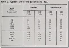
Additive effects of noise levels in work areas create the need for a wide range of available motor sound power levels at the same horsepower rating. The specified sound level depends upon the fractional contribution permitted for each motor (or any other source) in a particular workplace. Table 2 indi cates some typical noise levels of both standard and low-noise motors, which vary by manufacturer. Assuming that the standard values fall within the requirements of the workplace compo sition of noise sources, they can be specified d irectly. Otherwise, detailed noise specifications must be written. Th e values given in Table 2 are sound power levels. Power levels have replaced pressure levels as a standard for motor noise specification to remove acoustical differences in test and installation environments. The dBA le\’els are based on a hearing threshold of 1 picowatt (10- 12 watt) rather than 20 micropascals. Sound-pressure level correspondingly depends not only on the sound power level of the source but also on the distance from the source the space surrounding the source. This refinement in measurement of sound power ]pvel is necessary to ensure that all motors claiming an 84-dBA sound level have indeed been tested under similar conditions. The purchaser thus can compare apples and apples instead of apples and oranges.
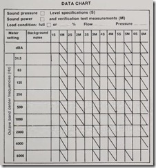
When specifications for specially fabricated low-noise equipment are written, they should include a data chart similar to the one shown. Using noise specification data determined according to good acoustical practice, all applicable requirements available at the time of purchase must be filled in. This information should include specified sound levels and microphone loca tions where measured sound-power levels are not available.
Test verification of sound levels should be entered in the data chart side-by-sirle with the specified data. The report format should include such considerations as acoustical instrumen tation used in the test, acoustical char acteristics of the test facility, location of equipment within the test facility, description of equipment mounting and installation for test, description of interfacing equipment, test loading of equipment, and microphone locations considering the differing approaches to level measurements and related data documentation. A II data sheets should be properly filled out, dated and signed by persons conducting the tests and by chaser. Failure to achieve noise specifi cations should be considered to be as relevant as any other equipment-per formance deficiency.
With quiet motors, industrial noise levels potentially harmful to workers can be reduced by source engineering controls . Through research, testing,and cooperation with vendors -and by specifying low noise levels for motors purchased- Du Pont is continuing its program to improve noise control in the workplace. This approach would seem well suited for noise reduction of though it takes a firm commitment and many years to accomplish.
