REAR MAIN BEARING OIL SEAL
It is important that oil be prevented from leak ing out of the rear main bearing, not only for the sake of oil economy but also because it may ruin the clutch facings if the car has a clutch.
Some engines have a single piece rubber seal which is fit to the groove in the flange at the rear of the block.
However, the most widely used type of rear main bearing oil seal is shown in Fig. 35. It con sists of two lengths of wicking or fabric, the upper and lower halves being carried in suitable grooves in the bearing struct ure. The illustration shows the lower seal in the bearing cap.
To renew any type of rear main bearing oil seal, it is obviously necessary to remove the oil pan. Renewing the lower oil seal only will very often stop the leak. However, whenever the crankshaft is removed for other work, it is good practice to install new seals, both upper and lower, regardless of how eff ective th ey appear to be.
In servicin g th e most common type of oil seal, Fig. 35, bear in mind that the materials used for side seals of this type includ e synthetic rubber or cork, fibre composition or wood blocks manufac tured to the correct size. In replacing these side seals, use th e same material as removed unless an other ma terial h as been substituted by the car maker.
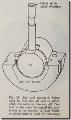
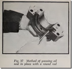
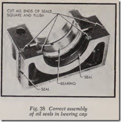
To replace the seal, remove the rear main bear ing cap and bearing insert. Take out the old seal, clean the groove and install a length of the new seal with the ends sticking up above the face of the cap. Force the seal firmly in place by means of the tool shown in Fig. 36. Lacking this tool or its equivalent, at least use a round rod to force the seal in the groove, Fig. 37. With the side seals installed, the cap assembly should be as shown in Fig. 38.
Although the usual practice is to remove the crankshaft when the upper half of the seal is to be replaced it is possible to do a satisfactory job without removing the crankshaft as follows:
To remove the seal, use needle-nosed pliers to grasp the end of the seal most accessible. Pull the seal downward while rotating the crankshaft slowly in the direction that the seal is being removed.
To install the new seal, fasten a length of wire or strong string such as fishing line securely to one end of the new seal. See that the point of fasten ing is not bulky and that it is not over %” from the end of the seal. Coat the seal with Lubriplate. Pass the free end of the wire or string up over the crankshaft at the point where the seal is to be installed. Then exert a firm, steady pull on the wire or string and at the same time rotate the crankshaft slowly in the direction of the pull. This will help to move the seal in position. When the installation is completed, trim the ends of the seal flush with the engine block.
One-Piece Rubber Seal
Fig. 39 illustrates the one-piece seal used on a number of engines. The seal does not fit in a groove. Instead it .fits on the flange which forms the rear of the bearing bore. The lip of the seal presses against the oil slinger on the crankshaft. Leakage is thus prevented.
The oil seal is pulled out with a pair of pliers after the bearing cap has been removed, Fig. 40. Then the new seal is slid into place, Fig. 41. How ever, the details of the operation are as follows:
Remove engine oil pan and clutch housing pan (if used).
Loosen all main bearing cap screws three turns to provide adequate clearance for inserting new seal.
To install a new seal, first lubricate its ends with cup grease, tire soap or glycerine. Wipe off any lubricant on the end faces. Start one end onto the flange in the block and push it up until it is near the top. Then work the other end into place. Spread some of the lubricant on the groove in the seal so that the bearing cap will slip readily into place.
The lip of the seal that contacts the crankshaft should be coated with oil before installing the cap to prevent scuffing the seal.
When installing the seal, be sure that the seal ing lip is adjacent to the oil slinger and not backwards. Oil leakage can be expected if lip faces rear.
CRANKSHAFT REMOVAL
Although it is possible to remove the crankshaft on many cars without removing the engine from the chassis it is not practical because the usual reasons for taking out the crankshaft are for major service operations that can be done best with the engine out of the car.
With the engine out of the car, mount it on an engine stand or on a low workbench. Remove cylinder head or heads, manifolds, etc. with en gine right side up. Then turn engine upside down and remove oil pan, vibration damper, fan pulley, flywheel, timing case cover, etc. Take out the pistons and rods. Be sure the main bearing caps are suitably marked as to their location before re moving them. Then lift out the crankshaft.
HAND POLISHING CRANKSHAFT
If crankshaft journals are slightly rough or burred they can be smoothed up by hand with No. 320 grit emery cloth or a fine honing stone. In either case, wet the journal with engine oil.
CRANKSHAFT GRINDER
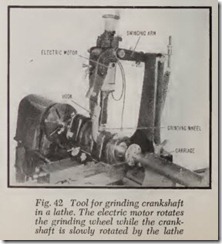
Grinding a crankshaft is a job for an automotive machine shop. The work requires a skilled opera tor and an expensive machine made for the pur pose. However, the portable fixture shown in Fig. 42 is designed for regrinding crankshaft journals when the crankshaft is mounted in a lathe. The fixture is clamped to the lathe carriage.
The adjustable hook is placed under the jour nal. Its purpose is to hold the grinding wheel in contact with the journal surface. When a rod journal is ground the hook and the grinding wheel reciprocate up and down because they are linked to the swinging arm.
The same grinding wheel unit can be used for grinding rod journals when the engine is in the ear-in conjunction with a fixture that is clamped to the underside of the crankcase.
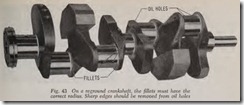
On reground crankshafts it is most important for the oil holes and the fillets, Fig. 43, to blend smoothly into the journal surface. The fillet radius on the reground shaft should be the same as for a new shaft. If the radius is too large the edges of the bearing may wear rapidly. If too small, the crankshaft may crack in time and break at one of the fillets.
Other causes of crankshaft breakage include:
1. Bending due to misalignment of bearings.
2. Bending due to improper main journal grinding.
3. Bending due to the weight of an overhung fly wheel.
4. Torsional vibration.
The last two, of course are faults of design, and there is nothing the mechanic can do about it. The first two, though, can be avoided by taking suffi cient care in the measurement and assembly of the engine.
Practically all crankshafts are hardened to a certain extent by either of two basic processes. One is called Tocco hardening, and is a process by which the main journal and crankpin areas are hardened to an appreciable depth. These crank shafts can be reground because the hardening reaches a depth of at least .050″.
The other, called Tufftriding, hardens the crankshaft all over. This a low temperature salt bath nitriding process used to increase wear re sistance and fatigue life of steel parts subject to high operating stresses. It can be applied to any steel crankshafts or other parts regardless of whether they were Tufftrided in original manufac ture or not.
The hardened skin produced by Tufftriding is very shallow, only .0003″ to .0005″ thick. An intermediate layer of .015″ to .018″ thickness be low the thin hardened surface will not give good crankshaft life. Therefore Tufftrided shafts are not suitable for grinding unless they are re-hardened, and this is a specialized process for which few shops are equipped.
To check any shaft to determine if it has been Tufftrided, either of two methods may be used.
First, a chemical method. A drop of 10% aque ous solution of copper ammonium chloride (which can usually be obtained from your local pharmacy) is placed on the shaft. If the solution turns from its light blue color to a reddish brown (copper) color in less than 10 seconds, the shaft has not been Tufftridcd. The time element is important. If the color change takes longer than
10 seconds, the shaft has probably been Tuff trided.
Second, a file test method. A sharp medium-fine mill file is applied to any crankshaft surface other than tlte journals, such as a crank cheek. If metal can be removed under light pressure, the shaft has not been Tufftrided, and may be reground. If the file glides over the surface and no metal is re moved, the shaft has been Tufftridcd and cannot be reground without re-hardening.
Quite a large number of crankshafts are Tuff trided in original manufacture, by almost all makers, and it is therefore highly desirable that all shafts be checked by either of the above methods before sending them out for grinding.
MAIN BEARING BORES OUT-OF-ROUND
Crankshaft main bearing bores may go out-of round in use. If they are out-of-round more than .002″, main bearing life will be reduced. The remedy is to install semi-finished main bearings and line bore them to size. Check bores with in side micrometer.
WARPED MAIN BEARING CAPS
It is a good plan to check main bearing caps for flatness whenever they are removed, Fig. 44. A warped cap may cause reduced oil pressure and increased oil consumption. Warped caps should either be discarded or trued up by grinding or filing the cap as indicated in Fig. 44 but be careful not to go below the edges of the bearing bore. If the material is removed with a file, finish the surface smooth with emery cloth. Lay the cloth on a flat surface, wet it with engine oil and rub the cap back and forth until it is smooth.
WARPED CRANKCASE
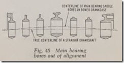
If the main bearing bores are out of alignment more than .002″, Fig. 45, bearing life will be re duced. The greater this misalignme nt the shorter the bearing life. The cure is to install semi-finished main bearings and line bore them to size.
CHECK CRANKSHAFT STRAIGHTNESS
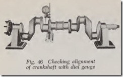
Whenever the crankshaft is removed it should be checked for straightness. Mount it in V blocks supporting the end main bearing journals, Fig. 46, and place a dial gauge in contact with one of the intermediate or center journals. Rotate the crank shaft through one revolution. If the dial gauge hand varies more than .003″, the crankshaft should be straightened in an arbor press.
Some authorities claim that it is not good prac tice to straighten a crankshaft because it will go out of alignment again. They prefer to true the crankshaft up by regrinding the journals. Obvi ously, if a crankshaft is a few thousandths out of line, regrinding the journals to .010″ undersize will correct the condition-or regrind the .020″ undersize, etc. The point is that by the very nature of the regrinding process, the finished journals are automatically brought into line.
FLYWHEEL SERVICE
If the surface of the flywheel is scored, cracked or burned, it should be refinished in a lathe. If more than a slight amount of metal must be removed, a new flywheel should be installed. It is important that the rear surface of th e flywheel be smooth to avoid undue wear of the clutch facing.
Also examine the flywheel bolt holes. If these are worn (due to running with a loose flywheel) the flywheel should be renewed. In other words, the bolts should fit into the bolt holes rather snugly.
Before installing the flywheel on the crankshaft, check th e clutch shaft pilot bearing in the crank shaft for wear, and be sure that th e mating sur faces are clean and free from burrs. Put the flywheel in place on the crankshaft and install and tighten th e bolts securely.
Check Flywheel Run-Out
Mount a dial indicator on the flywheel as shown in Fig. 47. If the run-out is more than .008″, remove the flywheel from th e crankshaft and ex amine all contacting surfaces for burrs and dirt. If any are found, remove them. Then install the flywh eel on the crankshaft and check the run-out again. If the run-out is caused by an untrue crank shaft or flywheel, the condition can be corrected by an automotive machine shop.
Flywheel Ring Gear, Replace
If the starter ring gear has some broken teeth or if the teeth are badly worn or chipped, the gear should be replaced with a new one. If a new gear is to be installed, remove the flywheel from the crankshaft. Then cut the ring gear part way through with a hacksaw and use a cold chisel to cut the gear all the way through. The gear usually falls off when split.
While removing the gear, support the flywheel on flat blocks of wood, with the front face of the flywheel upward. The blocks should be located within the circumference of the gear so as not to interfere with its removal.
Before installing the new gear, be sure to re move any dirt or rough spots from the flywheel surface that contacts the ring gear and do likewise for the inner circumference of the gear.
Note that the chamfered teeth on the gear should be on the “same side” as th e starter pinion. In other words, if the pinion is forward of the flywheel the chamfered teeth should be forward when installed on the flywheel-and should point rearward if the starter pinion is to the rear of the flywheel. Remember that the teeth are chamfered to make it easier for the pinion to engage the ring gear.
To install the ring gear on the flywheel, the gear is expanded by heating and then the flywheel is slipped into it.
To do this, place the ring gear on a flat plate on the floor. Take a piece of soldering wire the length of the ring gear circumference and lay it carefully on the upper face of the gear. Press it down against the gear so that it makes good contact at all points. Warm the gear slowly with a welding torch, running the flame around and around the gear. Do not direct the flame at th e solder. When the gear is warm enough to melt the solder all around, brush off the solder and insert the fly wheel into the gear. Be sure that the gear is tight against the flange on the flywheel. When the gear has cooled, it should be perfectly tight on the flywheel.
PREPARING CRANKSHAFT FOR HIGH PERFORMANCE
One of the most important operations in pre paring a high performance engine is balancing. This is highly specialized work and is only per formed in specially equipped shops. It involves removal of metal at heavy spots and the addition of metal at light spots.
Not only must the crankshaft itself be balanced, but the entire rotating and reciprocating assembly must be balanced together. This includes con necting rods, pistons, rings, and bearings, together with flywheel, clutch, vibration damper, fan pul ley, and timing gears.
Review Questions
|
26. When using Plastigage for checking bearing clearance, what would a well-flattened strip of this material indicate? . . . . . . . . . . . . . . . . . . . . . . . . . . . . . . . . . .
27. What would be the result of a Plastigage test if the crankshaft were accidentally moved?
28. What should be the position of the crankshaft journal for any rod bearing that is being measured by the shim or Plastigage method? . . . . . . . . . . . . . . . . . . . . . . . . . . . . . . . . . . . . . .
29. What parts of an engine should be cleaned before new bearings are installed? . . . . . . . . . .
30. Why are bearings made so that they project slightly above the bearing cap before assembly? . . . . . . . . . . . . . . . . . . . . . . . . . . . . . . . . . . . . . . . .
31. Explain how “bearing spread” aids in bearing installation. . . . . . . . . . . . . . . . . . . . . . . . . . . . .
32. What two methods might be used to keep main bearings from turning with the crankshaft?
33. On most engines the upper main bearing can be removed with the crankshaft in place. How is this accomplished without damaging the bearing surfaces? . . . . . . . . . . . . . . . . . . . .
34. One of the main bearings in any engine is of a special type. What is this bearing called?
35. How is crankshaft end play determined? . . . . . . . . . . . . . . . . . . . . . . . . . . . . . . . . . . . . . . . . . .
36. What reason other than oil economy is there for an effective rear main bearing oil seal? . …………………………………
37. Explain the difference between a rear main bearing oil seal and a rear main bearing cap side seal. . . . . . . . . . . . . . . . . . . . . . . . . . . . . . . . . . . . . . . . . .
38.Describe the most common type of rear main bearing oil seal. . . . . . . . . . . . . . . . . . . . . . . . .
39. Is it always best to remove an engine for crankshaft removal even though this operation might be performed with the engine in the chassis? . . . . . . . . . . . . . . . . . . . . . . . . . . . . . . . . . .
40. How is the starter ring fastened on the flywheel when it is not welded? . . . . . . . . . . . . . . . .

![fig39_thumb[1] fig39_thumb[1]](http://machineryequipmentonline.com/electric-equipment/wp-content/uploads/2020/06/fig39_thumb1_thumb.jpg)
![Fig. 40 The old one-piece rub¬_thumb[1] Fig. 40 The old one-piece rub¬_thumb[1]](http://machineryequipmentonline.com/electric-equipment/wp-content/uploads/2020/06/Fig.-40-The-old-one-piece-rub%C2%AC_thumb1_thumb.jpg)
![Fig. 41 The one-piece oil seal is pushed_thumb[1] Fig. 41 The one-piece oil seal is pushed_thumb[1]](http://machineryequipmentonline.com/electric-equipment/wp-content/uploads/2020/06/Fig.-41-The-one-piece-oil-seal-is-pushed_thumb1_thumb.jpg)
