Bendix Electronic Injection (EFI)
Bendix Electronic Fuel Injection ( EFI) basi cally involves electrically actuated fuel metering valves which, when actuated, spray a predeter mined quantity of fuel into the engine. These valves or injectors are mounted in the intake mani f old with the metering tip pointed toward the head of the intake valve. This arrangement is com monly known as port injection. The injector open ing is timed in accordance with the engine fre quency so that the fuel change is in place prior to the intake stroke for the cylinder.
Gasoline is supplied to the inlet of the injectors through the fuel rail at high enough pressure to obtain good fuel atomization and to prevent vapor f ormation in the fuel system during extended hot operation. When the solenoid operated valves are energized the injector metering valve (pintle) moves to the full open position and since the pres sure differential across the valve is constant , the fuel quantity is changed by varying the time that the injector is held open.
The injectors could be energized all at one time (called continuous injection) or one after the other in phase with the opening of each intake valve (called sequential injection) or they can be ener gized in groups.
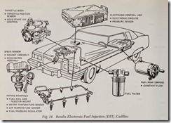
The Cadillac EFI System, Fig. 14, is a two group system. In a two-group system, the eight in jectors are divided into two groups of four each. Cylinders 1, 2, 7 and 8 form group 1 while group 2 consists of cylinders 3, 4, 5 and 6. All four in jectors in a group are opened and closed simul taneously while the groups operate alternately.
The amount of air entering the engine is mea sured by monitoring intake manifold absolute pressure, the inlet air temperature, and the engine speed (in rpm). This information allows the Elec-
tronic Control Unit to compute the flow rate of air being inducted into the engine, and consequently, the flow rate of fuel required to achieve the de sired air/fuel ratio for the particular engine oper ating condition. Each of the groups is activated once for every revolution of the camshaft and two revolutions of the crankshaft.
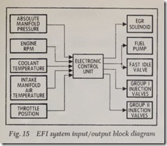
The input/output block diagram, Fig. 15, rep resents Cadillac’s two group EFI system. In this system, the prevailing engine conditions are moni tored with sensors and provide information to the Electronic Control Unit (ECU). The ECU con verts the multi-variable input information into an injector pulse width, which opens the injectors for the proper duration and at the proper time with respect to the cylinder firing sequence.
The object of the ECU is to calculate fuel re quirements for the engine for various combinations of inputs from the sensors, to determine an injector pulse width and provide accurate control of the air/fuel ratio.
SYSTEM DESCRIPTION
The EFI System is comprised of four major sub- systems:
1. Fuel Delivery ,
2. Air Induction ,
3. Sensors, and
4. Electronic Control Unit. The function of these separate subsystems is integrated into the system operation.
Fuel Delivery
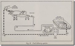
The fuel delivery system, Fig. 16, includes an in-tank boost pump, a chassis-mounted constant displacement fuel pump, a fuel filter, the fuel rails,
one injector for each cylinder, a fuel pressure regu lator, and supply and return lines. The fuel pumps are activated by the electronic control unit ( ECU) when the ignition is turned on and the engine is cranking or operating. (If the engine stalls or if the starter is not engaged, the fuel pumps will de activate in approximately one second.) Fuel is pumped from the fuel tank through the supply line and the filter to the fuel rails. The injectors supply fuel to the engine cylinders in precisely timed bursts controlled by the electrical signals from the ECU. Excess fuel is returned to the fuel tank.
Fuel Delivery System Components Fuel Tank
The fuel tank used on cars equipped with EFI incorporates a reservoir directly below the sending unit-in-tank pump assembly. The “bath tub” shaped reservoir is used to insure a constant sup ply of fuel for the in-tank pump, even at low fuel level and severe maneuvering conditions. The fuel returned to the tank by the fuel pressure regulator is dumped directly into the reservoir as an addi tional means of keeping the pump intake below the fuel level.
In-Tank Boost Pump
Two electric fuel pumps are used with the EFI system. Located inside the fuel tank and an inte gral part of the fuel gage tank unit, the in-tank pump is used to supply fuel to the chassis mounted pump and to prevent vapor lock on the suction side of the system.
The chassis-mounted and in-tank fuel pumps are electrically connected parallel to the ECU and are protected by an AGC-10 fuse located in the harness near the ECU.
Chassis-Mounted Fuel Pump
The Chassis-mounted fuel pump is a constant displacement, roller-vane pump driven by a 12 volt motor. The pump incorporates a check valve to prevent back-flow. This maintains fuel pressure when the pump is off. The pump has a flow rate of 33 gallons per hour under normal operating con ditions ( 39 PSI). An internal relief valve provides over-pressure protection by opening at an exces sive pressure ( $5-95 PSI). The pump is mounted under the vehicle, forward of the left rear wheel on all except Eldorado vehicles, and forward of the right rear wheel on the Eldorado.
Fuel Filter
The Fu el Filter consists of a casing with an in ternal paper filter element capable of filtering foreign particles down to the 20 micron size. The filter element is a throwaway type and should be serviced regularly.
Fuel Pressure Regulator
The Fuel Pressure Regulator contains an air chamber and fuel chamber separated by a spring loaded diaphragm. The air chamber is connected by a rubber hose to the throttle body assembly.
The pressure in this chamber is identical to the pressure of the intake manifold. The changing manifold pressure and the spring control th e ac tion of the diaphragm valve, opening or closing an orifice in the fuel chamber. (Excess fuel is re turned to the fuel tank.) This regulator, being con nected to the fuel rail and intake manifold, main tains a constant 39 psi differential across the in jectors.
The fuel pressure regulator is mounted on the fuel rail toward the front of the engine.
Injection Valve
The Injection Valve is a solenoid operated pintle valve that meters fuel to each cylinder. Based upon a pulsed signal from the electronic control unit, the valve opens for the proper time interval (pulse-width) to deliver the exact amount of fuel required. When energized, the valve sprays the fuel in fine droplets. When de-energized, it pre vents further fuel .Bow to the engine. Handling of the injection valve requires special care to avoid possible damage to the metering tip. The injection valves are located on the intake manifold above the intake valve for each cylinder.
Air Induction
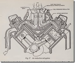
The Air Induction subsystem, Fig. 17, consists of the throttle body assembly, fast idle valve as sembly, and intake manifold.
Air for combustion enters the throttle body and is distributed to each cylinder through the intake manifold. The primary air Bow rate is controlled by the throttle valves which are connected to the accelerator pedal linkage. An adjustable idle by pass air passage is incorporated within the throttle body that allows a regulated amount of air to by pass the throttle valves. The throttle blades are also pre-set slightly open when the throttle lever is resting against the idle stop position. This ad justment is not to be altered.
Additional air for cold starts and warm-up is provided through an electrically controlled fast idle valve, which is incorporated in the top of the throttle body.
Air Induction System Components Intake Manifold
The dual plane intake manifold is basically the same for EFI equipped vehicles as for carburetor equipped vehicles. The EFI intake manifold dif fers from the carburetor version in the following ways:
1. Only air is distributed to the intake port through the intake manifold.
2. The manifold contains a port above each cylinder for injection valve installation. The fuel is injected directly toward the top of the cylinder intake valve.
3./A port is available to receive the air tempera ture sensor.
4. No exhaust heat passage is used. The exhaust passages from the right cylinder head are used only for EGR.
5. The EGR passage delivers exhaust gas from the right cylinder head to an area just ahead of the manifold bores under the throttle body and then into the manifold.
Throttle Body
The throttle body, Fig. 17, consists of a housing with two bores and two shaft mounted throttle valves connected to the vehicle accelerator pedal by mechanical linkage. Fittings are incorporated to accommodate vacuum connections. The end of the throttle shaft opposite from the accelerator lever, controls the throttle position switch (de scribed below under Engine Sensors). An adjust able set screw on the front of the throttle body enables adjustment of warm engine idle speed Turning the screw clockwise restricts the air Bow passing through the idle air channel, lowering the
engine speed (rpm). Turning the screw counter clockwise permits a greater air flow, thereby in creasing the engine idle speed.
A large post on top of the throttle body contains the fast idle valve.
Fast Idle Valve
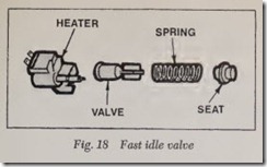
The fast idle valve, Fig. 18, consists of a plastic body that houses an electric heater, a spring and plunger and a thermal sensitive element.
The device is installed in the top of the throttle body. Electrically, it is connected to the fuel pump circuit through the electronic control unit. When the cold engine is started, the open valve allows supplemental air to bypass the throttle. The heater warms the thermal element which expands, forcing the spring and plunger toward the orifice, reduc ing the supplemental air flow and thus reducing the engine speed to the normal level. The fast idle valve will have no further effect after the thermal element reaches approximately 140° F. (60° C.). The rate of valve closure is a function of time and temperature. The warmer the ambient tempera ture, the faster the valve will close, reducing the engine idle speed. At 68° F. (20° C.), the valve will close in approximately 90 seconds; at -20° F. ( -29° C.), the valve will require approximately 5 minutes to close.
Engine Sensors
The sensors are electrically connected to the Electronic Control Unit and all operate indepen dently of each other. Each sensor transmits a sig nal to the ECU, relating a specific engine operat ing condition. The ECU analyzes all the signals and transmits the appropriate commands.
Manifold Absolute Pressure Sensor (MAP)
Manifold Absolute Pressure (MAP) Sensor monitors the changes in intake manifold pressure controlled by engine load, speed and barometric pressure variations. These pressure changes are supplied to the electronic control unit circuitry in the form of electrical signals. The sensor also monitors the changes in the intake manifold pres sure due to changes in altitude. As intake mani fold pressure increases, additional fuel is required. The MAP sensor sends this information to the ECU so that the pulse width will be increased. Conversely, as manifold pressure decreases the pulse width will be shortened.
The sensor is mounted within the electronic control unit. A manifold pressure line, routed with the engine harness, connects it to the front of the throttle body.
Throttle Position Switch
The Throttle Position Switch is mounted on the throttle body and connected to the throttle valve shaft. Movement of the accelerator causes the throttle shaft to rotate (varying the opening of the throttle blades ) . The switch senses the shaft move ment and position (closed throttle, wide open throttle, or position changes), and transmits ap propriate electrical signals to the electronic control unit. The electronic control unit processes these signals to determine the fuel requirement for the particular situation.
Temperature Sensors
The Temperature Sensors (Coolant and Air) are comprised of a coil of high temperature nickel wire sealed into an epoxy case, and molded into a brass housing with two wires and a connector ex tending from the body. The resistance of the wire changes as a function of temperature. Low tem peratures provide low resistan ce and as tempera tures increase, so does resistance. The voltage drop , across each sensor is monitored by the ECU.
The Air Temperature Sensor is located on the rear side of the intake manifold and is connected to the engine harness. The Coolant Temperature Sensor is located on the heater hose fittings at the rear of the right cylinder head.
Both temperature sensors are identical and completely interchangeable.
Speed Sensor
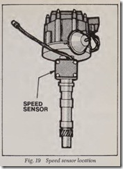
The Speed Sensor is incorporated within the special ignition distributor assembly (REI), Fig.19. It consists of two components. The first has two reed switches mounted to a plastic housing. The housing is affixed to the distributor shaft housing. The second is a rotor with two magnets, attached to and rotating with the distributor shaft.
The rotor rotates past the reed switches causing them to open and close. This provides two types of information: synchronization of the ECU and the proper injector group with the intake valve timing (phasing); and the engine rpm for fueJ scheduling.
Electronic Control Unit (ECU)
The electronic control unit is a preprogrammed analog computer consisting of custom electronic circuits housed in a steel case. The unit is installed above the glove box within the passenger compart
ment. It is electrically connected to the vehicle power supply and the other EFI components by a harness that is routed through the firewall.
The ECU receives power from the vehicle bat tery when the ignition is set to the ON or CRANK position. During cranking and engine operation, the following events occur.
Information Received from EFI Sensors
1. Engine Coolant Temperature
2. Intake Manifold Air Temperature
3. Intake Manifold Absolute Pressure
4. Engine Speed and Firing Position
5. Throttle Position and Change of Position
Commands Transmitted by ECU
1. Electric Fuel Pump Activation
2. Fast Idle Valve Activation
3. Injection Valve Activation
4. EGR Solenoid Activation
The desired air/fuel ratios for various driving and atmospheric conditions are designed into the ECU. As the above signals are received from the sensors, the ECU processes the signals and com putes the engine’s fuel requirements. The ECU issues commands to the injection valves to open for a specified time duration. The duration of the command pulses varies as the operating conditions change. All injection valves in each group open simultaneously upon command.
The EFI System is activated when the ignition switch is turned to the ON position. The follow ing events occur at that moment:
1. The Electronic Control Unit (ECU) receives vehicle battery voltage.
2. The Fuel Pumps are activated by the ECU. (The pumps will operate for approximately one second only, unless the engine is cranking or run- ning.) ·
3. All engine sensors are activated and begin transmitting signals to the ECU.
4. The electrically heated Fast Idle Valve is activated. (The Fast Idle Valve is connected to the Fuel Pump electrical circuit and like the fuel pumps, will only be activated for approximately one second unless the engine is cranking or run ning. ‘This action is controlled by the ECU.)
5. The EGR solenoid is activated, blocking the vacuum signal to the EGR valve at coolant tem peratures below 130° F. ( 60° C;).
The following events occur when the engine is started:
1. The Fuel Pumps are activated for continuous operation.
2. The heater element of the Fast Idle Valve is activated for continuous operation.
3. The Throttle Body air-bypass controls the air flow to the intake manifold with the throttle valves closed. When the vehicle accelerator is depressed, the throttle valves open, creating an air flow simi lar to a carburetor.
4. The Fuel Pressure Regulator maintains the fuel pressure in the Fuel Rail (Injector inlet) at 39 psi higher than the intake manifold air pressure by returning excess fuel to the fuel tank.
5. The following signals from the primary sen sors are continuously received and processed by the Electronic Control Unit.
a. Engine Coolant Temperature
b. Intake Manifold Air Temperature
a. Intake Manifold Ansolute Air Pressure
b. Engine speed and firing position
c. Throttle Position changes or wide open throt tle (W.O.T.) position
6. The ECU emits electrical signals alternately to each injector group, precisely controlling the opening and closing time (pulse width) to de liver fuel to the engine
