In this case scenario, the motor winding being tested is a nine-lead wye connection with shorted turns in phase A. The breakdown isn’t visible. It was operating on high voltage when it failed.
First, check the rotor winding by turning the shaft, using an ohmmeter or limited current. Compare the high/low readings as described earlier. (The stator winding can be checked more quickly and easily with the rotor removed, but it isn’t required.)
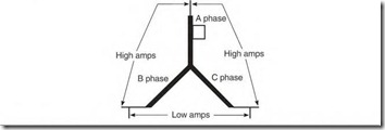
The motor’s shorted A-phase winding has less resistance than the B and C phases (Fig. 7.12). Because of the wye connection, there is lower resistance (or higher amperes) from the faulty phase lead (Tl) to both of the other phase leads (T2 and T3). When the two normal phases (T2 to T3) are checked, they will have higher resistance (or lower amperes) because the shorted turns aren’t included.
If more than one phase has shorted turns, all three phases will have different readings.
FIGURE 7.12 A single-circuit wye-connected motor with an open phase.
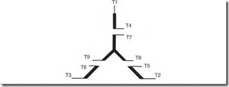
If the short isn’t visible, the exact location of the shorted turns can be determined by disconnecting leads T4 and T7. Compare the circuits Tl to T4, T2 to T5, and T3 to T6. If the test results of circuits T2 to T5 and T3 to T6 are identical, but different from that for Tl to T4, the problem lies between Tl and T4.
Now cut the tie cord and carefully lift the Tl lead. If the short is found close to Tl (within the first two to three turns), the breakdown may have been caused by a voltage spike.
If the Tl to T4, T2 to T5, and T3 to T6 test results are identical, compare T7 to T8, T8 to T9, and T9 to T7. Record the lead number that shows a difference to both of the other leads in the circuit. A problem in this circuit wouldn’t be spike-related unless the motor had been operating on its lowvoltage connection.
Locating Voltage Spike Damage in a
Wye-Connected Nine-Lead Motor
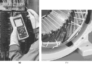
Voltage spike damage has increased with the use of variable-hertz drives. This problem can be reduced with properly placed reactors, surge capacitors, or tuned filters. Power quality test instruments can be used to determine the likelihood of spike-causing conditions. Figure 7.13a shows an instrument used for this test.
Spike damage occurrences increase when the distance between the control and the motor is more than 50 feet. This will cause a breakdown within the first two to three turns of a line lead. This breakdown characteristic is unique to spikes and is easy to identify (Fig. 7.13b).
If the motor was operating on low voltage, test each circuit separately, as shown in Fig. 7.14. The leads that connect to lines are Tl and T7 for line l,
FIGURE 7.13 (a) Testing the power quality with a handheld oscilloscope. Fluke. (b) Winding damaged by a spike. EASA.
FIGURE 7.14 Check points for finding spike damage in a nine-lead wye-connected motor (connected low voltage).
T2 and T8 for line 2, and T3 and T9 for line 3. If the damage is not visible, each identical circuit should be comparison-tested (Tl to T4, T2 to T5, T3 to T6, T7 to T8, T8 to T9, and T9 to T7).
A brief description of the breakdown and its location should be entered in the motor’s software for future reference.
Locating Shorted Turns in a Delta-Connected Nine-Lead Motor
In this case scenario, the motor winding being tested is a nine-lead delta connection, with shorted turns in phase A. The breakdown isn’t visible. It was operating on high voltage when it failed (Fig. 7.15).
First, check the rotor winding by turning the shaft and comparing the high and low readings. (The stator winding can also be comparison-tested with the rotor removed.)
The motor’s A-phase winding has shorted turns. This means it has less resistance than the B and C phases (Fig. 7.16). Because of the delta connection, there will be lower resistance (or higher amperes) across the faulty phase leads Tl to T2. When the two normal phases (T2 to T3 and T3 to
High resistance Tl Low
High resistance
FIGURE 7.15 Checkpoints for locating a shorted phase in a nine-lead delta connection (connected high voltage).
FIGURE 7.16 A shovted A phase in a nine-lead delta connection (connected high voltage) gives the above test results.
T l) are checked, they will have higher resistance (or lower amperes) because the shorted turns aren’t included. Some current will flow through the faulty phase when the normal phases are tested. This current will affect both normal phases the same, and the readings will be identical. All three phases will have different readings if more than one phase has shorted turns.
The exact location of the shorted turns can be determined by disconnecting all leads and comparing the identical circuits. Identical circuits are from Tl to T4 and from Tl to T9. They should have the same readings if there are no problems. The same is true from T2 to T5, T2 to T7, T3 to T6 and T3 to T8.
The comparison test shows less resistance (or higher amperes) between Tl and T4, which locates the shorted turns. Check the shorted turns between Tl and T4 for a possible spike-caused breakdown.
If the delta-connected motor is operating on low voltage, a spike-caused breakdown will occur close to any lead connected to a line. The low-voltage connection subjects all leads to spike damage (Fig. 7.17).
The location of the shorted coils may point to the cause of the breakdown. (A current-conducting contaminant that settles on a winding will affect the coils that it covers.)
FIGURE 7.17 All leads are subject to spike damage when connected low voltage.
A brief description of the breakdown and its location should be entered into the motor’s software for future reference.
Megohmmeter Test for Ground
A megohmmeter (see Chapter 8) is a popular instrument for testing slot insulation. The test is done from a winding lead to the frame. A megohmmeter will show infinity when the winding is good.
If the megohmmeter shows from 2 to 50 megohms to the motor’s frame, the motor can still be used, but it should be cleaned and baked dry at the earliest convenience. Follow with a varnish treatment. (The chemical components of new varnish must be compatible with the original varnish.)
Moisture-caused breakdown usually occurs at the bottom side of the lowest coil in the stat0L (A water line is often visible on the bottom coils.) This type of breakdown is normally from the winding to the frame (ground) in the lowest slot.
Conducting contaminants cause breakdown in the areas where they accumulate. Breakdowns will occur on top of the top coils, and on the top of the bottom coils.
Be sure to ground the motor leads to the frame after the test.


![clip_image002[5] clip_image002[5]](http://machineryequipmentonline.com/electric-equipment/wp-content/uploads/2017/05/clip_image0025_thumb.gif)
![clip_image002[5] clip_image002[5]](http://machineryequipmentonline.com/electric-equipment/wp-content/uploads/2017/05/clip_image0025_thumb1.jpg)
![clip_image002[7] clip_image002[7]](http://machineryequipmentonline.com/electric-equipment/wp-content/uploads/2017/05/clip_image0027_thumb.jpg)