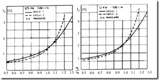
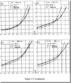
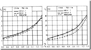
The AIM has been applied to 12 different three-phase IMs from 0.75 kW to 15 kW (two-pole and four-pole motors), to calculate both the magnetization curve I10 = f(E1) and the core losses on no load for various voltage levels.
The magnetizing current is Iµ = I1r and the no load active current I0A is I0A= Fe 3mvV0 copper The no-load current I10 is thus (5.82) I10 = Iµ2 + I0A2 (5.83) and E1 ≈ V0 − ω1L1σI10 (5.84)
where L1σ is the stator leakage inductance (known). Complete expressions of leakage inductances are introduced in Chapter 6.
Figure 5.15 exhibits computation results obtained with the conventional nonlinear model, the proposed model, and experimental data.
Figure 5.15 Magnetization characteristic validation on no load
1. conventional nonlinear model (paragraph 5.4.1); 2. AIM; 3. experiments
Figure 5.15 (continued)
Figure 5.15 (continued)
It seems clear that AIM produces very good agreement with experiments even for high saturation levels.
A few remarks on AIM seem in order.
The slotting is only globally accounted for by defining different tangential and radial permeabilities in the stator and rotor teeth.
A single, but variable, permeability characterizes each of the machine domains (teeth and back cores).
AIM is a bi-directional field approach and thus both radial and tangential flux density components are calculated.
Provided the rotor equivalent current Ir (RMS value and phase shift with respect to stator current) is given, AIM allows calculation of the distribution of main flux in the machine on load.
Heavy saturation levels (V0/Vn > 1) are handled satisfactorily by AIM.
By skewing the stack axially, the effect of skewing on main flux distribution can be handled.
The computation effort is minimal (a few seconds per run on a contemporary PC).
So far AIM was used considering that the spatial field distribution is sinusoidal along stator bore. In reality, it may depart from this situation as shown in the previous paragraph. We may repeatedly use AIM to produce the actual spatial flux distribution or the airgap flux harmonics.
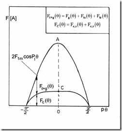
AIM may be used to calculate saturation-caused harmonics. The total mmf F1m is still considered sinusoidal (Figure 5.16).
The maximum airgap flux density Bg1m (sinusoidal in nature) is considered known by using AIM for given stator (and eventually also rotor) current RMS values and phase shifts.
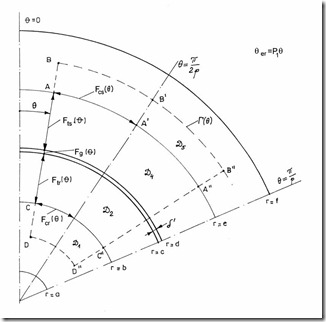
By repeatedly using the Ampere’s law on contours such as those in Figure 5.17 at different position θ, we may find the actual distribution of airgap flux density, by admitting that the tangential flux density in the back core retains the sinusoidal distribution along θ. This assumption is not, in general, far from reality as was shown in paragraph 5.4.3.
Ampere’s law on contour Γ (Figure 5.17) is
P1θ
∫Hdl = ∫F1m sinp1θd p( 1θ =) 2F1m cosp1θ (5.85)
Γ − θP1
The left side of (5.85) may be broken into various parts (Figure 5.17). It may easily be shown that, due to the absence of any mmf within contours ABB′B′′A′′A′A and DCC′′D′′,
∫ Hdl = ∫Hdl; ∫Hdl = ∫Hdl (5.86)
ABB’A”B”A” AA” CDD”C” CC”
Figure 5.16 Ampere’s law contours
Figure 5.17 Mmf–total and back core component F
We may now divide the mmf components into two categories: those that depend directly on the airgap flux density Bg(θ) and those that do not (Figure 5.17).
2Ft +g = 2Fg ( )θ + 2Fts ( )θ + 2Ftr ( )θ (5.87)
Fc ( )θ = Fcs ( )θ + Fcr ( )θ (5.88)
Also, the airgap mmf Fg(θ) is
Fg ( )θ = gKµ0c Bg ( )θ (5.89)
Suppose we know the maximum value of the stator core flux density, for given F1m, as obtained from AIM, Bcsm,
Bcs ( )θ = Bcsm sinp1θ (5.90)
We may now calculate Fcs(θ) as
π/ 2
Fcs ( )θ = 2 ∫[Hcs (Bcsm sinα)]edα (5.91)
p1θ
The rotor core maximum flux density Bcrm is also known from AIM for the same mmf F1m. The rotor core mmf Fcr(θ) is thus
Fcr ( )θ = 2π∫/ 2[Hcr (Bcrm sinα)]bdα (5.92)
p1θ
From (5.88) Fc(θ) is obtained. Consequently,
Ft +g = 2F1m cospθ − Fcr ( )θ − Fcs ( )θ (5.93)
Now in (5.87) we have only to express Fts(θ) and Ftr(θ)–tooth mmfs–as functions of airgap flux density Bg(θ). This is straightforward.
−1
Bts ( )θ = βξss Bg ( )θ ; ξ =s bτtss (5.94)
τs–stator slot pitch, bts–stator tooth, βs < 1–ratio of real and apparent tooth flux density (due to the flux deviation through slot). Similarly, for the rotor,
Btr ( )θ = βξ1r Bg ( )θ ; ξ =r bτtrr −1 (5.95)
Now Ft+g ( )θ = 2Bg0( )θ µg0 + 2h Hs ts βξss Bg ( )θ + 2h Hr tr βξrr Bg ( )θ (5.96)
In (5.96) Ft+g(θ) is known for given θ from (5.93). Bg0(θ) is assigned an initial value in (5.96) and then, based on the lamination B/H curve, Hts and Htr are calculated. Based on this, Ft+g is recalculated and compared to the value from (5.93). The calculation cycle is reiterated until sufficient convergence is reached.
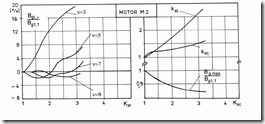
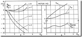
The same operation is performed for 20 to 50 values of θ per half-pole to obtain smooth Bg(θ), Bts(θ), Btr(θ) curves per given stator (and rotor) mmfs (currents). Fourier analysis is used to calculate the harmonics contents. Sample results concerning the airgap flux density distribution for three designs of the same motor are given in Figures 5.18 though 5.21. [8]
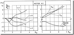
Figure 5.18 IM with equally saturated teeth and back cores
Figure 5.19 IM with saturated teeth (Kst > Ksc)
Figure 5.20 IM with saturated back cores
a.) airgap flux density b.) saturation factors Kst, Ksc, versus total saturation factor Ks
The geometrical data are
M1–optimized motor = equal saturation of teeth and cores: a = 0.015 m, b =
0.036 m, c = 0.0505 m, d = 0.051 m, e = 0.066 m, f = 0.091 m, ξs = 0.54, ξr = 0.6
M2–oversaturated stator teeth (Kst > Ksc): b = 0.04 m, e = 0.06 m, ξs = 0.42, ξr = 0.48
M3–oversaturated back cores (Ksc > Kst): b = 0.033 m, e = 0.069 m, ξs = 0.6, ξr = 0.65
The results on Figure 5.18 – 5.21 may be interpreted as follows:
If the saturation level (factor) in the teeth and back cores is about the same (motor M1 on Figure 5.21), then even for large degrees of saturation (Ks = 2.6 on Figure 5.18b), the airgap flux harmonics are small (Figure 5.18a).
This is why a design may be called optimized.
If the teeth and back core saturation levels are notably different (oversaturated teeth is common), then the harmonics content of airgap flux density is rich. Flattened airgap flux distribution is obtained for oversaturated back cores (Figure 5.20). 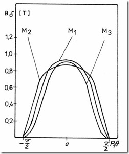
Figure 5.21 Airgap flux density distribution for three IM designs, M1, M2, M3.
The above remarks seem to suggest that equal saturation level in teeth and back iron is to be provided to reduce airgap flux harmonics content. However, if core loss minimization is aimed at, this might not be the case, as discussed in Chapter 11 on core losses.

