INDUSTRIAL TRANSDUCERS
Ultrasonic transducers
Sound that is generated beyond the level of human hearing range is called ultrasound. Although ultrasound typically starts at 20 kHz, most ultrasonic transducers start at 200 kHz. Ultrasound, which is similar in nature to audible sound, has far shorter wavelengths and is suitable for detecting small flaws. These shorter wavelengths make ultrasound extremely useful for non-destructive testing and measurement of materials. An ultrasonic transducer itself is a device that is capable of generating and receiving ultrasonic vibrations.
An ultrasonic transducer is made up of an active element, a backing, and a wear plate. The active element is a piezoelectric or single crystal material, which converts electrical energy to ultrasonic energy. It also receives back ultrasonic energy and converts this to electrical energy. The electrical energy pulse is generated in an instrument such as a flaw detector.
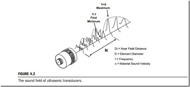
The sound field of an ultrasonic transducer has two distinct zones, as indicated in Figure 4.2. These zones are called the near field, which is the region directly in front of the transducer, and the far field, which is the area beyond N where the sound field pressure gradually drops to zero. The near-field distance is a function of the transducer frequency, element diameter, and the sound velocity of the test material, as shown in the following equation:
ðFigure 4:2 gives the definitions for N; D; and CÞ N ¼ D2=4c:
There are several sound field parameters that are very useful in describing the characteristics of an ultrasonic transducer. Knowledge of the focal length, beam width and focal zone may be necessary in
order to determine whether a particular transducer is appropriate for an application. The beam angle is the total included angle of ultrasonic beam. In general, a high-frequency transducer will produce a narrow beam and a lower-frequency transducer a wider beam.
All transducers have beam spread, which is important when inspecting flaws that may be close to certain geometric features of the material to be tested, including side walls and corners that may cause spurious echoes which could be mistaken for flaws or defects. For flat transducers the pulse-echo beam spread angle, a, is well defined and is given by the equation:
Sine ða=2Þ ¼ 0:514c=fD:
It can be seen from this equation that beam spread in a transducer can be reduced by selecting a transducer with a higher frequency, or a larger diameter, or both.
Ultrasonic transducers are classified into two groups according to the application.
(1) Contact transducers
Contact transducers are used for direct contact inspections, and are generally hand manipulated. They have elements that are protected in a rugged casing to withstand sliding contact with a variety of materials. These transducers have an ergonomic design so that they are easy to grip and move along a surface. They often have replaceable wear plates to lengthen their useful life. Coupling materials of water, grease, oils, or commercial fluids are used to remove the air gap between the transducer and the component being inspected.
(2) Immersion transducers
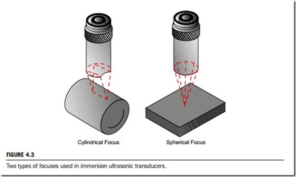
Immersion transducers do not contact the component. These transducers are designed to operate in a liquid environment, and so all connections are watertight. Immersion transducers usually have an impedance matching layer that helps to get more sound energy into the water and, in turn, into the component being inspected. Immersion transducers can have a cylindrically or spherically focused lens, as shown in Figure 4.3. A focused transducer can improve its sensitivity and axial resolution by concentrating the sound energy to a smaller area. They are typically used inside a water tank, or as part of a squinter or bubbler system in scanning applications.
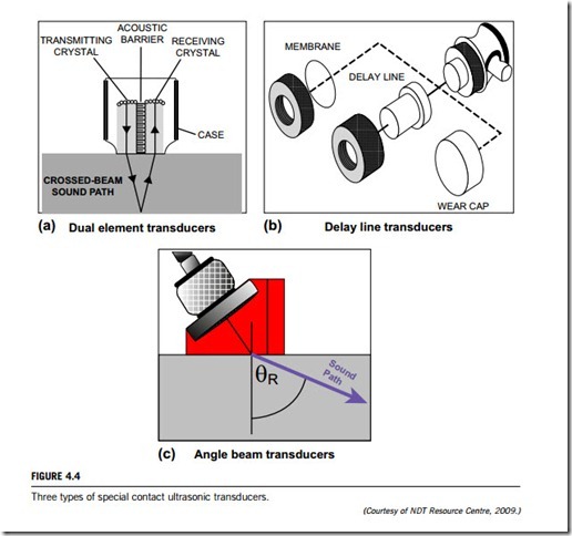
Contact transducers are available in a variety of configurations to improve their adaptability. Three examples are detailed below.
(1) Dual-element transducers contain two, independently operated elements in a single housing. One of the elements transmits and the other receives the ultrasonic signal. These two elements are angled towards each other to create a crossed-beam sound path in the test material. Figure 4.4(a) shows the operating principle of dual-element transducers. Active elements can be chosen for their transmission and receiving capabilities to provide a transducer with a cleaner signal, or designed for special applications, such as the inspection of coarse-grained material. Dual-element transducers are especially well suited for making measurements in applications where reflectors are very near the transducer, since this design eliminates the ring-down effect that single-element transducers experience.
(2) Delay line transducers provide versatility by having a variety of replaceable options. As shown in Figure 4.4(b), delay line transducers have a removable delay line, a surface conforming membrane, and protective wear cap options. These components can make a single transducer effective for a wide range of applications. The primary function of a delay line transducer is to introduce a time delay
between the generation of the sound wave and the arrival of any reflected waves. This allows the transducer to complete its sending function before it starts its listening function, so that near surface resolution is improved. They are designed for use in applications such as high-precision thickness gauging of thin materials and delaminating checks in composite materials. They are also useful in high-temperature measurement applications, since the delay line provides some insulation from heat to the piezoelectric element.
(3) Angle beam transducers are typically used to introduce a refracted shear wave into the test material. Transducers can use a variety of fixed angles, or in adjustable versions where the user determines the angles of incidence and refraction. In the fixed-angle versions, the angle of refraction that is marked on the transducer is only accurate for a particular material, which is usually steel. The angled sound path allows the sound beam to be reflected from the back wall of the target to improve detectability of flaws in and around welded areas. They are also used to generate surface waves for use in detecting defects on the surface of a component. Figure 4.4(c) shows the operating principle of angle beam transducers.
Linear and rotary variable differential transformers
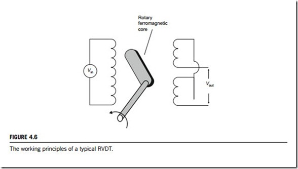
The linear variable differential transformer (LVDT) is a well-established transducer design which has been used for many decades for the accurate measurement of displacement, and within closed loops for the control of positioning. The rotational variable differential transformer (RVDT) is also a well- established transducer design used to measure rotational angles and operates under the same principles as the LVDT sensor. Whilst the LVDT has a cylindrical iron core, the RVDT has a rotary ferromagnetic core.
Both the LVDT and RVDT designs lend themselves to easy modification in order to fulfil a whole range of different applications in both research and industry. This includes pressurized versions for hydraulic applications, materials suitable for sea water and marine services, dimensions to suit specific application requirements, multichannel, rack amplifier-based systems, automotive suspension systems.
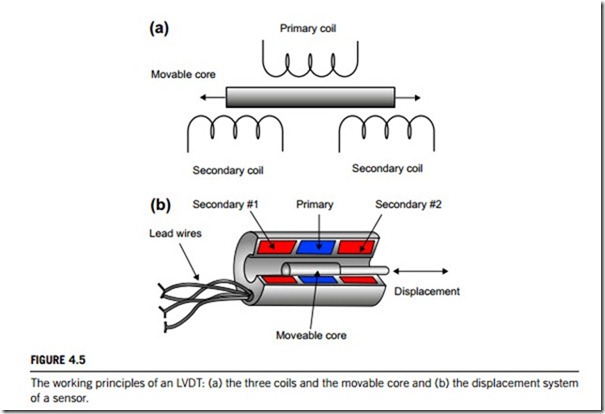
(1) An LVDT is much like any other transformer, in that it consists of a primary coil, secondary coils, and a magnetic core as illustrated in Figure 4.5(a). The primary coils (the upper coil in Figure 4.5(a)) are energized with constant-amplitude alternating current. This produces an alternating
magnetic field in the center of the transducer, which induces a signal into the secondary coils (the two lower coils in Figure 4.5(a)) depending on the position of the core.
Movement of the core within this area causes the secondary signal to change (Figure 4.5(b)). As the two secondary coils are positioned and connected in a set arrangement (push pull mode), when the core is positioned at the center, a zero signal is produced. Movement of the core from this point in either direction causes the signal to increase. Since the coils are wound in a particular precise configuration, the signal output has a linear relationship with the actual mechanical movement of the core.
The secondary output signal is then processed by a phase-sensitive demodulator which is switched at the same frequency as the primary energizing supply. This results in a final output which, after rectification and filtering, gives direct current output that is proportional to the core movement, and also indicates its direction, positive or negative, from the central zero point (Figure 4.5(b)).
As with any transformer, the voltage of the induced signal in the secondary coil is linearly related to the number of coils. The basic transformer relation is:
Vout=Vin ¼ Nout=Nin;
where Vout is the voltage at the output, Vin is the voltage at the input, Nout is the number of windings of the output coil, and Nin is the number of windings of the input coil.
The distinct advantage of using an LVDT displacement transducer is that the moving core does not make contact with other electrical components of the assembly, which does occur in resistive types, and so offers high reliability and long life. Further, the core can be so aligned that an air gap exists around it, which is ideal for applications where minimum mechanical friction is required.
(2) An RVDT is an electromechanical transducer that provides a variable alternating current output voltage. This output voltage is linearly proportional to the angular displacement of its input shaft. When energized with a fixed alternating current source, the output signal is linear within a specified range of the angular displacement. RVDT utilizes brushless, noncontacting technology to ensure long life, reliability, and repeatable position sensing with infinite resolution. Such reliable and repeatable performance ensures accurate position sensing under the most extreme operating conditions.
As shown in Figure 4.6, rotating a ferromagnetic-core bearing that is supported within a housed stator assembly is the basis of RVDT construction and operation. The housing is stainless steel. The stator consists of a primary excitation coil and a pair of secondary output coils. A fixed, alternating current excitation is applied to the primary stator coil that is electromagnetically coupled to the secondary coils. This coupling is proportional to the angle of the input shaft. The output pair is structured so that one coil is in phase with the excitation coil, and the second is 180o out of phase with it. When the rotor is in a position that directs the available flux equally to both the in phase and out of phase coils, the output voltages cancel and result in a zero output signal. This is referred to as the electrical zero position. When the rotor shaft is displaced from the electrical zero position, the resulting output signals have a magnitude and phase relationship which is proportional to the direction of rotation.
Because the performance of an RVDT is essentially similar to that of a transformer, excitation voltage changes will produce directly proportional changes in the output (transformation ratio). However, the voltage out to excitation voltage ratio will remain constant. Since most RVDT signal conditioning systems measure signal as a function of the transformation ratio, excitation voltage drift beyond 7.5% typically has no effect on sensor accuracy and strict voltage regulation is not typically necessary. Excitation frequency should be controlled within ± 1% to maintain accuracy.
