Chapter 11: Network Organization and Architecture
11.1 Introduction
—Sun Microsystems, Inc.
Sun Microsystems launched a major advertising campaign in the 1980s with the catchy slogan that opens this chapter. A couple of decades ago, its pitch was surely more sizzle than steak, but it was like a voice in the wilderness, heralding today’s wired world with the Web at the heart of global commerce. Standalone business computers are now obsolete and irrelevant.
This chapter will introduce you to the vast and complex arena of data communications with a particular focus on the Internet. We will look at architectural models (network protocols) from a historical point of view, a theoretical point of view, and a practical point of view. Once you have an understanding of how a network operates, you will learn about many of the components that constitute network organization. Our intention is to give you a broad view of the technologies and terminology that every computer professional will encounter at some time during his or her career. To understand the computer is to also understand the network.
11.2 Early Business Computer Networks
Today’s computer networks evolved along two different paths. One path was directed toward enabling fast and accurate business transactions, whereas the other was aimed at facilitating collaboration and knowledge sharing in the academic and scientific communities.
Digital networks of all varieties aspire to share computer resources in the simplest, fastest, and most cost-effective manner possible. The more costly the computer, the stronger the motivation to share it among as many users as possible. In the 1950s, when most computers cost millions of dollars, only the wealthiest companies could afford more than one system. Of course, employees in remote locations had as much need for computer resources as their central office counterparts, so some method of getting them connected had to be devised. And virtually every vendor had a different connectivity solution. The most dominant of these vendors was IBM with its Systems Network Architecture (SNA). This communications architecture, with modifications, has persisted for over three decades.
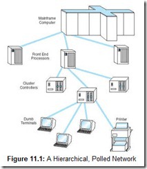
IBM’s SNA is a specification for end-to-end communication between physical devices (called physical units, or PUs) over which logical sessions (known as logical units, or LUs) take place. In the original architecture, the physical components of this system consisted of terminals, printers, communications controllers, multiplexers, and front-end processors. Front-end processors sat between the host (mainframe) system and the communications lines. They managed all of the communications overhead including polling each of the communications controllers, which in turn polled each of their attached terminals. This architecture is shown in Figure 11.1.
IBM’s SNA was geared toward high-speed transaction entry and customer service inquiries. Even at the modest line speed of 9600bps (bits per second), access to data on the host was nearly instantaneous when all network components were functioning properly under normal loads. The speed of this architecture, however, came at the expense of flexibility and interoperability. The human overhead in managing and supporting these networks was enormous, and connections to other vendors’ equipment and networks were often laudable feats of software and hardware engineering. Over the past 30 years, SNA has adapted to changing business needs and networking environments, but the underlying concepts are essentially what they were decades ago. In fact, this architecture was so well designed that aspects of it formed the foundation for the definitive international communications architecture, OSI, which we discuss in Section 11.4. Although SNA contributed much to the young science of data communications, the technology has just about run its course. In most installations, it has been replaced by “open” Internet protocols.
11.3 Early Academic and Scientific Networks — The Roots and Architecture of the Internet
Amid the angst of the Cold War, American scientists at far-flung research institutions toiled under government contracts, seeking to preserve the military ascendancy of the United States. At a time when we had fallen behind in the technology race, the United States government created an organization called the Advanced Research Projects Agency (ARPA). The sophisticated computers this organization needed to carry out its work, however, were scarce and extremely costly—even by Pentagon standards. Before long, it occurred to someone that by establishing communication links into the few supercomputers that were scattered all over the United States, computational resources could be shared by innumerable like-minded researchers. Moreover, this network would be designed with sufficient redundancy to provide for continuous communication, even if thermonuclear war knocked out a large number of nodes or communication lines. To this end in December 1968, a Cambridge, Massachusetts, consulting firm called BBN (Bolt, Beranek and Newman, now Genuity Corporation) was awarded the contract to construct such a network. In December 1969, four nodes, the University of Utah, the University of California at Los Angeles, the University of California at Santa Barbara, and the Stanford Research Institute, went online. ARPAnet gradually expanded to include more government and research institutions. When President Reagan changed the name of ARPA to the Defense Advanced Research Projects Network (DARPA), ARPAnet became DARPAnet. Through the early 1980s, nodes were added at a rate of a little more than one per month. However, military researchers eventually abandoned DARPAnet in favor of more secure channels.
In 1985, the National Science Foundation established its own network, NSFnet, to support its scientific and academic research. NSFnet and DARPAnet served a similar purpose and a similar user community, but the capabilities of NSFnet outstripped those of DARPAnet. Consequently, when the military abandoned DARPAnet, NSFnet absorbed it, and became what we now know as the Internet. By the early 1990s, the NSF had outgrown NSFnet, so it began building a faster, more reliable NSFnet. Administration of the public Internet then fell to private national and regional corporations, such as Sprint, MCI, and PacBell, to name a few. These companies bought the NSFnet trunk lines, called backbones, and made money by selling backbone capacity to various Internet service providers (ISPs).
The original DARPAnet (and now the Internet) would have survived thermonuclear war because, unlike all other networks in existence in the 1970s, it had no dedicated connections between systems. Information was instead routed along whatever pathways were available. Parts of the data stream belonging to a single dialogue could take different routes to their destinations. The key to this robustness is the idea of datagram message packets, which carry data in chunks instead of the streams used by the SNA model. Each datagram contains addressing information so that every datagram can be routed as a single, discrete unit.
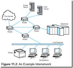
A second revolutionary aspect of DARPAnet was that it created a uniform protocol for communications between dissimilar hosts along networks of differing speeds. Because it connected many different kinds of networks, DARPAnet was said to be an internetwork. As originally specified, each host computer connected to DARPAnet by way of an Interface Message Processor (IMP). IMPs took care of protocol translation from the language of DARPAnet to the communications language native to the host system, so any communications protocol could be used between the IMP and the host. Today, routers (discussed in Section 11.6.7) have replaced IMPs, and the communications protocols are less heterogeneous than they were in the 1970s. However, the underlying principles have remained the same, and the generic concept of internetworking has become practically synonymous with the Internet. A modern internetwork configuration is shown in Figure 11.2. The diagram shows how four routers form the heart of the network. They connect many different types of equipment, making decisions on their own as to how datagrams should get to their destinations in the most efficient way possible.
The Internet is much more than a set of good data communication specifications. It is, perhaps, a philosophy. The foremost principle of this philosophy is the idea of a free and open world of information sharing, with the destiny of this world being shaped collaboratively by the people and ideas in it. The epitome of this openness is the manner in which Internet standards are created. Internet standards are formulated through a democratic process that takes place under the auspices of the Internet Architecture Board (IAB), which itself operates under the oversight of the not-for-profit Internet Society (ISOC). The Internet Engineering Task Force (IETF), operating within the IAB, is a loose alliance of industry experts that develops detailed specifications for Internet protocols. The IETF publishes all proposed standards in the form of Requests for Comment (RFCs), which are open to anyone’s scrutiny and comment. The two most important RFCs—RFC 791 (Internet Protocol Version 4) and RFC 793 (Transmission Control Protocol)—form the foundation of today’s global Internet.
The organization of all the ISOC’s committees under more committees could have resulted in a tangle of bureaucracy producing inscrutable and convoluted specifications. But owing to the openness of the entire process, as well as the talents of the reviewers, RFCs are among the clearest and most readable documents in the entire body of networking literature. It is little wonder that manufacturers were so quick to adopt Internet protocols. Internet protocols are now running on all sizes of networks, both publicly and privately owned. Formerly, networking standards were handed down by a centralized committee or through an equipment vendor. One such approach resulted in the ISO/OSI protocol model, which we discuss next.
11.5 Network Protocols II — TCP/IP Network Architecture
While the ISO and the CCITT were haggling over the finer points of the perfect protocol stack, TCP/IP was rapidly spreading across the globe. By the sheer weight of its popularity within the academic and scientific communications communities, TCP/IP quietly became the de facto global data communication standard.
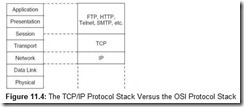
Although it didn’t start out that way, TCP/IP is now a lean and effective protocol stack. It has three layers that can be mapped to five of the seven layers in the OSI model. These layers are shown in Figure 11.4. Because the IP layer is loosely coupled with OSI’s Data Link and Physical layers, TCP/IP can be used with any type of network, even different types of networks within a single session. The singular requirement is that all of the participating networks must be running—at minimum—Version 4 of the Internet Protocol (IPv4).
There are two versions of the Internet Protocol in use today, Version 4 and Version 6. IPv6 addresses many of the limitations of IPv4. Despite the many advantages of IPv6, the huge installed base of IPv4 ensures that it will be supported for many years to come. Some of the major differences between IPv4 and IPv6 are outlined in Section 11.5.5. But first, we take a detailed look at IPv4.
11.5.1 The IP Layer for Version 4
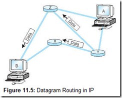
The IP layer of the TCP/IP protocol stack provides essentially the same services as the Network and Data Link layers of the OSI Reference Model: It divides TCP packets into protocol data units called datagrams, and then attaches the routing information required to get the datagrams to their destinations. The concept of the datagram was fundamental to the robustness of ARPAnet, and now, the Internet. Datagrams can take any route available to them without intervention by a human network manager. Take, for example, the network shown in Figure 11.5. If intermediate node X becomes congested or fails, intermediate node Y can route datagrams through node Z until X is back up to full speed. Routers are the Internet’s most critical components, and researchers are continually seeking ways to improve their effectiveness and performance. We look at routers in detail in Section 11.6.7.
The bytes that constitute any of the TCP/IP protocol data units are called octets. This is because at the time the ARPAnet protocols were being designed, the word byte was thought to be a proprietary term for the 8-bit groups used by IBM mainframes. Most TCP/IP literature uses the word octet, but we use byte for the sake of clarity.
![]()
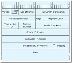
The IP Version 4 Datagram Header
Each IPv4 datagram must contain at least 40 bytes, which include a 24-byte header as shown above. The horizontal rows represent 32-bit words. Upon inspection of the figure, you can see, for example, that the Type of Service field occupies bits 8 through 15, while the Packet Identification field occupies bits 32 through 47 of the header. The Padding field shown as the last field of the header assures that the data that follows the header starts on an even 32-bit boundary. The Padding always contains zeroes. The other fields in the IPv4 header are:
-
Version—Specifies the IP protocol version being used. The version number tells all of the hardware along the way the length of the datagram and what content to expect in its header fields. For IPv4, this field is always 0100 (because 01002 = 410).
-
Header Length—Gives the length of the header in 32-bit words. The size of the IP header is variable, depending on the value of the IP Options fields, but the minimum value for a correct header is 5.
-
Type of Service—Controls the priority that the datagram is given by intermediate nodes. Values can range from “routine” (000) to “critical” (101). Network control datagrams are indicated with 110 and 111.
-
Total Length—Gives the length of the entire IP datagram in bytes. As you can see by the layout above, 2 bytes are reserved for this purpose. Hence, the largest allowable IP datagram is 216 – 1, or 65,535.
-
Packet ID—Each datagram is assigned a serial number as it is placed on the network. The combination of Host ID and Packet ID uniquely identifies each IP datagram in existence at any time in the world.
-
Flags—Specify whether the datagram may be fragmented (broken into smaller datagrams) by intermediate nodes. IP networks must be able to handle datagrams of at least 576 bytes. Most IP networks can deal with packets that are about 8KB long. With the “Don’t Fragment” bit set, an 8KB datagram will not be routed over a network that says it can handle only 2KB packets, for example.
-
Fragment Offset—Indicates the location of a fragment within a certain datagram. That is, it tells which part of the datagram the fragment came from.
-
Time to Live (TTL)—TTL was originally intended to measure the number of seconds for which the datagram would remain valid. Should a datagram get caught in a routing loop, the TTL would (theoretically) expire before the datagram could contribute to a congestion problem. In practice, the TTL field is decremented each time it passes through an intermediate network node, so this field does not really measure the number of seconds that a packet lives, but the number of hops it is allowed before it reaches its destination.
-
Protocol Number—Indicates which higher-layer protocol is sending the data that follows the header. Some of the important values for this field are:
0 = Reserved
1 = Internet Control Message Protocol (ICMP)
6 = Transmission Control Protocol (TCP)
17 = User Datagram Protocol (UDP)
TCP is described in Section 11.5.3.
-
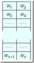
Header Checksum—This field is calculated by first calculating the one’s complement sum of all 16-bit words in the header, and then taking the one’s complement of this sum, with the checksum field itself originally set to all zeroes. The one’s complement sum is the arithmetic sum of two of the words with the (seventeenth) carry bit added to the lowest bit position of the sum. (See Section 2.4.2.) For example, 11110011 + 10011010 = 110001101 = 10001110 using one’s complement arithmetic. What this means is that if we have an IP datagram of the form shown to the right, each wi is a 16-bit word in the IP datagram. The complete checksum would be computed over two 16-bit words at a time: w1 + w2 = S1; S1 + w3 = S2; . . . Sk + wk–2 = Sk+1.
-
Source and Destination Addresses—Tell where the datagram is going. We have much more to say about these 32-bit fields in Section 11.5.2.
-
IP Options—Provides diagnostic information and routing controls. IP Options are, well, optional.
![]()
11.5.2 The Trouble with IP Version 4
The number of bytes allocated for each field in the IP header reflects the technological era in which IP was designed. Back in the ARPAnet years, no one could have imagined how the network would grow, or even that there would ever be a civilian use for it.
With the slowest networks of today being faster than the fastest networks of the 1960s, IP’s packet length limit of 65,536 bytes has become a problem. The packets simply move too fast for certain network equipment to be sure that the packet hasn’t been damaged between intermediate nodes. (At gigabit speeds, a 65,535-byte IP datagram passes over a given point in less than one millisecond.)
By far the most serious problem with IPv4 headers concerns addressing. Every host and router must have an address that is unique over the entire Internet. To assure that no Internet node duplicates the address of another Internet node, host IDs are administered by a central authority, the Internet Corporation for Assigned Names and Numbers (ICANN). ICANN keeps track of groups of IP addresses, which are subsequently allocated or assigned by regional authorities. (The ICANN also coordinates the assignment of parameter values used in protocols so that everyone knows which values evoke which behaviors over the Internet.)
As you can see by looking at the IP header shown in the sidebar, there are 232 or about 4.3 billion host IDs. It would be reasonable to think that there would be plenty of addresses to go around, but this is not the case. The problem lies in the fact that these addresses are not like serial numbers sequentially assigned to the next person who asks for one. It’s much more complicated than that.
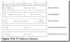
IP allows for three types, or classes, of networks, designated A, B, and C. They are distinguished from each other by the number of nodes (called hosts) that each can directly support. Class A networks can support the largest number of hosts; Class C, the least.
The first three bits of an IP address indicate the network class. Addresses for Class A networks always begin with 0, Class B with 10, and Class C with 110. The remaining bits in the address are devoted to the network number and the host ID within that network number, as shown in Figure 11.6.
IP addresses are 32-bit numbers expressed in dotted decimal notation, for example 18.7.21.69 or 146.186.157.6. Each of these decimal numbers represents 8 bits of binary information and can therefore have a decimal value between 0 and 255. 127.x.x.x is a Class A network but is reserved for loopback testing, which checks the TCP/IP protocol processes running on the host. During the loopback test no datagrams enter the network. The 0.0.0.0 network is typically reserved for use as the default route in the network.
Allowing for the reserved networks 0 and 127, only 126 Class A networks can be defined using a 7-bit network field. Class A networks are the largest networks of all, each able to support about 16.7 million nodes. Although it is unlikely that a Class A network would need all 16 million possible addresses, the Class A addresses, 1.0.0.0 through 126.255.255.255, were long ago assigned to early Internet adopters such as MIT and the Xerox Corporation. Furthermore, all of the 16,382 Class B network IDs (128.0.0.0 to 191.255.255.255) have also been assigned. Each Class B network can contain 65,534 unique node addresses. Because very few organizations need more than 100,000 addresses, their next choice is to identify themselves as Class C network owners, giving them only 256 addresses within the Class C space of 192.0.0.0 through 233.255.255.255. This is far fewer than would meet the needs of even a moderately sized company or institution. Thus, many networks have been unable to obtain a contiguous block of IP addresses so that each node on the network can have its own address on the Internet. A number of clever workarounds have been devised to deal with this problem, but the ultimate solution lies in reworking the entire IP address structure. We look at this new address structure in Section 11.5.6. (Classes D and E do exist, but they aren’t networks at all. Instead, they’re groups of reserved addresses. The Class D addresses, 224 through 240, are used for multicasting by groups of hosts that share a common characteristic. The Class E addresses, 241 through 248, are reserved for future use.)
In addition to the eventual depletion of address space, there are other problems with IPv4. Its original designers did not anticipate the growth of the Internet and the routing problems that would result from the address class scheme. There are typically 70,000-plus routes in the routing table of an Internet backbone router. The current routing infrastructure of IPv4 needs to be modified to reduce the number of routes that routers must store. As with cache memory, larger router memories result in slower routing information retrieval. There is also a definite need for security at the IP level. A protocol called IPSec (Internet Protocol Security) is currently defined for the IP level. However, it is optional and hasn’t been standardized or universally adopted.
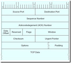
The TCP Segment Format
The TCP segment format is shown above. The numbers at the top of the figure are the bit positions spanned by each field. The horizontal rows represent 32-bit words. The fields are defined as follows:
-
Source and Destination Ports—Specifies interfaces to applications running above TCP. These applications are known to TCP by their port number.
-
Sequence Number—Indicates the sequence number of the first byte of data in the payload. TCP assigns each transmitted byte a sequence number. If 100 data bytes will be sent 10 bytes at a time, the sequence number in the first segment might be 0, the second 10, the third 20, and so forth. The starting sequence number is not necessarily 0, so long as the number is unique between the sender and receiver.
-
Acknowledgement Number—Contains the next data sequence number that the receiver is expecting. TCP uses this value to determine whether any datagrams have gotten lost along the way.
-
Data Offset—Contains the number of 32-bit words in the header, or equivalently, the relative location of the word where the data starts within the segment. Also known as the header length.
-
Reserved—These six bits must be zero until someone comes up with a good use for them.
-
Flags—Contains six bits that are used mostly for protocol management. They are set to “true” when their values are nonzero. The TCP flags and their meanings are:
URG: Indicates that urgent data exists in this segment. The Urgent Pointer field (see below) points to the location of the first byte that follows the urgent information.
ACK: Indicates whether the Acknowledgement Number field (see above) contains significant information.
PSH: Tells all TCP processes involved in the connection to clear their buffers, that is, “push” the data to the receiver. This flag should also be set when urgent data exists in the payload.
RST: Resets the connection. Usually, it forces validation of all packets received and places the receiver back into the “listen for more data” state.
SYN: Indicates that the purpose of the segment is to synchronize sequence numbers. If the sender transmits [SYN, SEQ# = x], it should subsequently receive [ACK, SEQ# = x + 1] from the receiver. At the time that two nodes establish a connection, both exchange their respective initial sequence numbers.
FIN: This is the “finished” flag. It lets the receiver know that the sender has completed transmission, having the effect of starting closedown procedures for the connection.
-
Window—Allows both nodes to define the size of their respective data windows by stating the number of bytes that each is willing to accept within any single segment. For example, if the sender transmits bytes numbered 0 to 1023 and the receiver acknowledges with 1024 in the ACK# field and a window value of 512, the sender should reply by sending data bytes 1024 through 1535. (This may happen when the receiver’s buffer is starting to fill up so it requests that the sender slow down until the receiver catches up.) Notice that if the receiver’s application is running very slowly, say it’s pulling data 1 or 2 bytes at a time from its buffer, the TCP process running at the receiver should wait until the application buffer is empty enough to justify sending another segment. If the receiver sends a window size of 0, the effect is acknowledgement of all bytes up to the acknowledgement number, and to stop further data transmission until the same acknowledgment number is sent again with a nonzero window size.
-
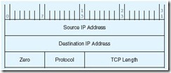
Checksum—This field contains the checksum over the fields in the TCP segment (except the data padding and the checksum itself), along with an IP pseudoheader as follows:
-
As with the IP checksum explained earlier, the TCP checksum is the 16-bit one’s complement of the sum of all 16-bit words in the header and text of the TCP segment.
-
Urgent Pointer—Points to the first byte that follows the urgent data. This field is meaningful only when the URG flag is set.
-
Options—Concerns, among other things, negotiation of window sizes and whether selective acknowledgment (SACK) can be used. SACK permits retransmission of particular segments within a window as opposed to requiring the entire window to be retransmitted if a segment from somewhere in the middle gets lost. This concept will be clearer to you after our discussion of TCP flow control.
![]()
11.5.3 Transmission Control Protocol
The sole purpose of IP is to correctly route datagrams across the network. You can think of IP as a courier who delivers packages with no concern as to their contents or the order in which they are delivered. Transmission Control Protocol (TCP) is the consumer of IP services, and it does indeed care about these things as well as many others.
The protocol connection between two TCP processes is much more sophisticated than the one at the IP layer. Where IP simply accepts or rejects datagrams based only on header information, TCP opens a conversation, called a connection, with a TCP process running on a remote system. A TCP connection is very much analogous to a telephone conversation, with its own protocol “etiquette.” As part of initiating this conversation, TCP also opens a service access point, SAP, in the application running above it. In TCP, this SAP is a numerical value called a port. The combination of the port number, the host ID, and the protocol designation becomes a socket, which is logically equivalent to a file name (or handle) to the application running above TCP. Instead of accessing data by using its disk file name, the application using TCP reads data through the socket. Port numbers 0 through 1023 are called “well-known” port numbers because they are reserved for particular TCP applications. For example, the TCP/IP File Transfer Protocol (FTP) application uses ports 20 and 21. The Telnet terminal protocol uses port 23. Port numbers 1024 through 65,535 are available for user-defined implementations.
TCP makes sure that the stream of data it provides to the application is complete, in its proper sequence, and with no duplicated data. TCP also compensates for irregularities in the underlying network by making sure that its segments (data packets with headers) aren’t sent so fast that they overwhelm intermediate nodes or the receiver. A TCP segment requires at least 20 bytes for its header. The data payload is optional. A segment can be at most 65,515 bytes long, including the header, so that the entire segment fits into an IP payload. If need be, IP can fragment a TCP segment if requested to do so by an intermediate node.
TCP provides a reliable, connection-oriented service. Connection-oriented means simply that the connection must be set up before the hosts can exchange any information (much like a telephone call). The reliability is provided by a sequence number assigned to each segment. Acknowledgements are used to verify that segments are received, and must be sent and received within a specific period of time. If no acknowledgement is forthcoming, the data is retransmitted. We provide a brief introduction to how this protocol works in the next section.
11.5.4 The TCP Protocol at Work
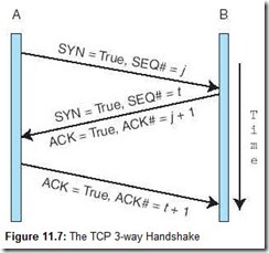
So how does all of this fit together to make a solid, sequenced, error-free connection between two (or more) TCP processes running on separate systems? Successful communication takes place in three phases: one to initiate the connection, a second to exchange the data, and a third to tear down the connection. First, the initiator, which we’ll call A, transmits an “open” primitive to a TCP process running on the remote system, B. B is assumed to be listening for an “open” request. This “open” primitive has the form:
If B is ready to accept a TCP connection from the sender, it replies with:
To which A responds:
A and B have now acknowledged each other and synchronized starting sequence numbers. A‘s next sequence number will be t + 2; B‘s will be j + 2. Protocol exchanges like these are often referred to as three-way handshakes. Most networking literature display these sorts of exchanges schematically, as shown in Figure 11.7.
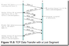
After the connection between A and B is established, they may proceed to negotiate the window size and set other options for their connection. The window tells the sender how much data to send between acknowledgments. For example, suppose A and B negotiate a window size of 500 bytes with a data payload size of 100 bytes, both agreeing not to use selective acknowledgement (discussed below). Figure 11.8 shows how TCP manages the flow of data between the two hosts. Notice what happens when a segment gets lost: The entire window is retransmitted, despite the fact that subsequent segments were delivered without error.
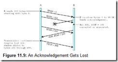
If an acknowledgment gets lost, however, a subsequent acknowledgement can prevent retransmission of the one that got lost, as shown in Figure 11.9. Of course, the acknowledgement must be sent in time to prevent a “timeout” retransmission.
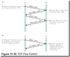
Using acknowledgement numbers, the receiver can also ask the sender to slow down or halt transmission. It is necessary to do so when the receiver’s buffer gets too full. Figure 11.10a illustrates how this is done. Figure 11.10b shows how B keeps the connection alive while it cannot receive any more data.
a. B tells A to slow down.
b. B keeps the connection alive while unable to receive more data.
Upon completion of the data exchange, one or both of the TCP processes gracefully terminates the connection. One side of the connection, say A, may indicate to the other side, B, that it is finished by sending a segment with its FIN flag set to true. This effectively closes down the connection from A to B. B, however, could continue its side of the conversation until it no longer has data to send. Once B is finished, it also transmits a segment with the FIN flag set. If A acknowledges B‘s FIN, the connection is terminated on both ends. If B receives no acknowledgement for the duration of its timeout interval, it automatically terminates the connection.
As opposed to having hard and fast rules, TCP allows the sender and receiver to negotiate a timeout period. The timeout should be set to a greater value if the connection is slower than when it is faster. The sender and receiver can also agree to use selective acknowledgement. When selective acknowledgement (SACK) is enabled, the receiver must acknowledge each datagram. In other words, no sliding window is used. SACK can save some bandwidth when an error occurs, because only the segment that has not been acknowledged (instead of the entire window) will be retransmitted. But if the exchange is error-free, bandwidth is wasted by sending acknowledgement segments. For this reason, SACK is chosen only when there is little TCP buffer space on the receiver. The larger the receiver’s buffer, the more “wiggle room” it has for receiving segments out of sequence. TCP does whatever it can to provide the applications running above it with an error-free, sequenced stream of data.
11.5.5 IP Version 6
By 1994, it appeared that IP’s Class B address problem was a crisis in the making, having the potential to bring the explosive growth of the Internet to an abrupt halt. Spurred by this sense of approaching doom, the IETF began concerted work on a successor to IPv4, now called IPv6. IETF participants released a number of experimental protocols that, over time, became known as IPv5. The corrected and enhanced versions of these protocols became known as IPv6. Experts predict that IPv6 won’t be widely implemented until late in the first decade of the twenty-first century. (Every day more Internet applications are being modified to work with IPv6.) In fact, some opponents argue that IPv6 will “never” be completely deployed because so much costly hardware will need to be replaced and because workarounds have been found for the most vexing problems inherent in IPv4. But, contrary to what its detractors would have you believe, IPv6 is much more than a patch for the Class B address shortage problem. It fixes many things that most people don’t realize are broken, as we will explain.
The IETF’s primary motivation in designing a successor to IPv4 was, of course, to extend IP’s address space beyond its current 32-bit limit to 128 bits for both the source and destination host addresses. This is an incredibly large address space, giving 2128 possible host addresses. In concrete terms, if each of these addresses were assigned to a network card weighing 28 grams (1 oz), 2128 network cards would have a mass 1.61 quadrillion times that of the entire Earth! So it would seem that the supply of IPv6 addresses is inexhaustible.
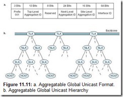
The down side of having such a large address space is that address management becomes critical. If addresses are assigned haphazardly with no organization in mind, effective packet routing would become impossible. Every router on the Internet would eventually require the storage and speed of a supercomputer to deal with the ensuing routing table explosion. To head off this problem, the IETF came up with a hierarchical address organization that it calls the Aggregatable Global Unicast Address Format shown in Figure 11.11a. The first 3 bits of the IPv6 address constitute a flag indicating that the address is a Global Unicast Address. The next 13 bits form the Top-Level Aggregation Identifier (TLA ID), which is followed by 8 reserved bits that allow either the TLA ID or the 24-bit Next-Level Aggregation Identifier (NLA ID) to expand, if needed. A TLA entity may be a country or perhaps a major global telecommunications carrier. An NLA entity could be a large corporation, a government, an academic institution, an ISP, or a small telecommunications carrier. The 16 bits following the NLA ID are the Site-Level Aggregation Identifier (SLA ID). NLA entities can use this field to create their own hierarchy, allowing each NLA entity to have 65,536 subnetworks, each of which can have 264 hosts. This hierarchy is shown graphically in Figure 11.11b.
The IP Version 6 Header
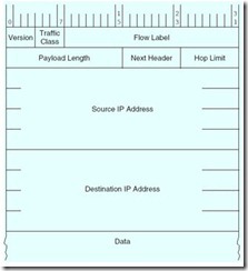
The obvious problem with IPv4, of course, is its 32-bit address fields. IPv6 corrects this shortcoming by expanding the address fields to 128 bits. In order to keep the IPv6 header as small as possible (which speeds routing), many of the rarely used IPv4 header fields are not included in the main header of IPv6. If these fields are needed, a Next Header pointer has been provided. With the Next Header field, IPv6 could conceivably support a large number of header fields. Thus, future enhancements to IP would be much less disruptive than the switch from Version 4 to Version 6 portends to be. The IPv6 header fields are explained below.
-
Traffic Class—IPv6 will eventually be able to tell the difference between real-time transmissions (e.g., voice and video) and less time-sensitive data transport traffic. This field will be used to distinguish between these two traffic types.
-
Flow Label—This is another field for which specifications are still in progress. A “flow” is a conversation, either broadcast to all nodes or initiated between two particular nodes. The Flow Label field identifies a particular flow stream and intermediate routers will route the packets in a manner consistent with the code in the flow field.
-
Payload Length—Indicates the length of the payload in bytes, which includes the size of additional headers.
-
Next Header—Indicates the type of header, if any, that follows the main header. If an IPv6 protocol exchange requires more protocol information than can be carried in a single header, the Next Header field provides for an extension header. These extension headers are placed in the payload of the segment. If there is no IP extension header, then this field will contain the value for “TCP,” meaning that the first header data in the payload belongs to TCP, not IP. In general, only the destination node will examine the contents of the extension headers. Intermediate nodes pass them on as if they were common payload data.
-
Hop Limit—With 16 bits, this field is much larger than in Version 4, allowing 256 hops. As in Version 4, this field is decremented by each intermediate router. If it ever becomes zero, the packet is discarded and the sender is notified through an ICMP (for IPv6) message.
-
Source and Destination Addresses—Much larger, but with the same meaning as in Version 4. See text for a discussion of the format for this address.
![]()
At first glance, the notion of making allowances for 264 hosts on each subnet seems as wasteful of address space as the IPv4 network class system. However, such a large field is necessary to support stateless address autoconfiguration, a new feature in IPv6. In stateless address autoconfiguration, a host uses the 48-bit address burned into its network interface card (its MAC address, explained in Section 11.6.2), along with the network address information that it retrieves from a nearby router to form its entire IP address. If no problems occur during this process, each host on the network configures its own address information with no intervention by the network administrator. This feature will be a blessing to network administrators if an entity changes its ISP or telecommunications carrier. Network administrators will have to change only the IP addresses of their routers. Stateless address autoconfiguration will automatically update the TLA or SLA fields in every node on the network.
The written syntax of IPv6 addresses also differs from that of IPv4 addresses. Recall that IPv4 addresses are expressed using a dotted decimal notion, as in 146.186.157.6. IPv6 addresses are instead given in hexadecimal, separated by colons, as follows:
30FA:505A:B210:224C:1114:0327:0904:0225
making it much easier to recognize the binary equivalent of an IP address.
IPv6 addresses can be abbreviated, omitting zeroes where possible. If a 16-bit group is 0000, it can be written as 0, or omitted altogether. If more than two consecutive colons result from this omission, they can be reduced to two colons (provided there is only one group of more than two consecutive colons). For example, the IPv6 address:
30FA:0000:0000:0000:0010:0002:0300
can be written:
30FA:0:0:0:10:2:300
or even
30FA::10:2:300
However, an address such as 30FA::24D6::12CB is invalid.
The IETF is also proposing two other routing improvements: implementation of multicasting (where one message is placed on the network and read by multiple nodes) and anycasting (where any one of a logical group of nodes can be the recipient of a message, but no particular receiver is specified by the packet). This feature, along with stateless address autoconfiguration, facilitates support for mobile devices, an increasingly important sector of Internet users, particularly in countries where most telecommunications take place over wireless networks.
As previously mentioned, security is another major area in which IPv6 differs from IPv4. All of IPv4’s security features (IPSec) are “optional,” meaning that no one is forced to implement any type of security, and most installations don’t. In IPv6, IPSec is mandatory. Among the security improvements in IPv6 is a mechanism that prevents address spoofing, where a host can engage in communications with another host using a falsified IP address. (IP spoofing is often used to subvert filtering routers and firewalls intended to keep outsiders from accessing private intranets, among other things.) IPSec also supports encryption and other measures that make it more difficult for miscreants to sniff out unauthorized information.
Perhaps the best feature of IPv6 is that it provides a transition plan that allows networks to gradually move to the new format. Support for IPv4 is built into IPv6. Devices that use both protocols are called dual stack devices, because they support protocol stacks for both IPv4 and IPv6. Most routers on the market today are dual stack devices, with the expectation that IPv6 will become a reality in the not too distant future.
The benefits of IPv6 over IPv4 are clear: a greater address space, better and built-in quality of service, and better and more efficient routing. It is not a question of if but of when we will move to IPv6. The transition will be driven by the business need for IPv6 and development of the necessary applications. Although hardware replacement cost is a significant barrier, technician training and replacement of minor IP devices (such as network fax machines and printers) will contribute to the overall cost of conversion. With the advent of IP-ready automobiles, as well as many other Internet devices, IPv4 no longer meets the needs of many current applications.
11.6 Network Organization
Computer networks are often classified according to their geographic service areas. The smallest networks are local area networks (LANs). Although they can encompass thousands of nodes, LANs typically are used in a single building, or a group of buildings that are near each other. When a LAN covers more than one building, it is sometimes called a campus network. Usually, the region (the property) covered by a LAN is under the same ownership (or control) as the LAN itself. Metropolitan area networks (MANs) are networks that cover a city and its environs. They often span areas that are not under the ownership of the people who also own the network. Wide area networks (WANs) can cover multiple cities, or span the entire world.
At one time, the protocols employed by LANs, MANs, and WANs differed vastly from one another. MANs and WANs were usually designed for high-speed throughput because they served as backbone systems for multiple slower LANs, or they offered access to large host computers in data centers far away from end users. As network technologies have evolved, however, these networks are now distinguished from each other not so much by their speed or by their protocols, but by their ownership. One person’s campus LAN might be another person’s MAN. In fact, as LANs are becoming faster and more easily integrated with WAN technology, it is conceivable that eventually the concept of a MAN may disappear entirely.
This section discusses the physical network components common to LANs, MANs, and WANs. We start at the lowest level of network organization, the physical medium level, Layer 1.
11.6.1 Physical Transmission Media
Virtually any medium with the ability to carry a signal can support data communication. There are two general types of communications media: Guided transmission media and unguided transmission media. Unguided media broadcast data over the airwaves using infrared, microwave, satellite, or broadcast radio carrier signals. Guided media are physical connectors such as copper wire or fiber optic cable that directly connect to each network node.
The physical and electrical properties of guided media determine their ability to accurately convey signals of given frequencies over various distances. In Chapter 7, we mentioned that signals attenuate (get weaker) over long distances. The longer the distance and the higher the signal frequency, the greater the attenuation. Attenuation in copper wire results from the interactions of several electrical phenomena. Chief among these are the internal resistance of copper conductors and the electrical interference (inductance and capacitance) that occurs when signal-carrying wires are in close proximity to each other. External electrical fields such as those surrounding fluorescent lights and electric motors can also attenuate—or even garble—signals as they are transmitted over copper wire. Collectively, the electrical phenomena that work against the accurate transmission of signals are called noise. Signal and noise strengths are both measured in decibels (dB). Cables are rated according to how well they convey signals at different frequencies in the presence of noise. The resulting quantity is the signal-to-noise rating for the communications channel, and it is also measured in decibels:
The bandwidth of a medium is technically the range of frequencies that it can carry, measured in hertz. The wider the medium’s bandwidth, the more information it can carry. In digital communications, bandwidth is the general term for the information-carrying capacity of a medium, measured in bits per second (bps). Another important measure is bit error rate (BER), which is the ratio of the number of bits received in error to the total number of bits received. If signal frequencies exceed the signal-carrying capacity of the line, the BER may become so extreme that the attached devices will spend more of their time doing error recovery than in doing useful work.
Coaxial Cable
Coaxial cable was once the medium of choice for data communications. It can carry signals up to trillions of cycles per second with low attenuation. Today, it is used mostly for broadcast and closed circuit television applications. Coaxial cable also carries signals for residential Internet services that piggyback on cable television lines.
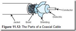
The heart of a coaxial cable is a thick (12 to 16 gauge) inner conductor surrounded by an insulating layer called a dielectric. The dielectric is surrounded by a foil shield to protect it from transient electromagnetic fields. The foil shield is itself wrapped in a steel or copper braid to provide an electrical ground for the cable. The entire cable is then encased in a durable plastic coating (see Figure 11.12).
The coaxial cable employed by cable television services is called broadband cable because it has a capacity of at least 2Mbit/second. Broadband communication provides multiple channels of data, using a form of multiplexing. Computer networks often use narrowband cable, which is optimized for a typical bandwidth of 64kbit/second, consisting of a single channel.
Twisted Pair
The easiest way to connect two computers is simply to run a pair of copper wires between them. One of the wires is used for sending data, the other for receiving. Of course, the further apart the two systems are from each other, the stronger the signal has to be to prevent them from attenuating into oblivion over long distances. The distance between the two systems also affects the speed at which data can be transferred. The further apart they are, the slower the line speed must be to avoid excessive errors. Using thicker conductors (smaller wire gauge numbers) can reduce attenuation. Of course, thick wire is more costly than thin wire.
In addition to attenuation, cable makers are also challenged by an electrical phenomenon known as inductance. When two wires lay perfectly flat and adjacent to each other, strong high-frequency signals in the wires create magnetic (inductive) fields around the copper conductors, which interfere with the signals in both lines.
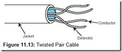
The easiest way to reduce the electrical inductance between conductors is to twist them together. To a point, the more twists that are introduced in a pair of wires per linear foot, the less attenuation that is caused by the wires interfering with each other. Twisted wire is more costly to manufacture than untwisted wire because more wire is consumed per linear foot and the twisting must be carefully controlled. Twisted pair cabling, with two twisted wire pairs, is used in most local area network installations today (see Figure 11.13). It comes in two varieties: shielded and unshielded. Unshielded twisted pair is the most popular.
Shielded twisted pair cable is suitable for environments having a great deal of electrical interference. Today’s business environments are teeming with sources of electromagnetic radiation that can interfere with network signals. These sources can be as seemingly benign as fluorescent lights or as obviously hostile as large, humming power transformers. Any device that produces a magnetic field has the potential for scrambling network communication links. Interference can limit the speed of a network because higher signal frequencies are more sensitive to any kind of signal distortion. As a safeguard against environmental interference (called electromagnetic interference [EMI] or radio-frequency interference [RFI]), shielded twisted pair wire can be installed to help maintain the integrity of network communications in hostile environments.
Experts disagree as to whether this shielding is worth the higher material and installation costs. They point out that if the shielding is not properly grounded, it can actually cause more problems than it solves. Specifically, it can act as an antenna that actually attracts radio signals to the conductors!
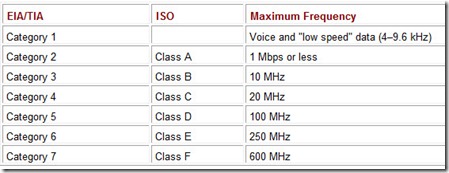
Whether shielded or unshielded, network conductors must have signal-carrying capacity appropriate to the network technology being used. The Electronic Industries Alliance (EIA), along with the Telecommunications Industry Association (TIA), established a rating system for network cabling in 1991. The latest revision of this rating system is EIA/TIA-568B. The EIA/TIA category ratings specify the maximum frequency that the cable can support without excessive attenuation. The ISO rating system, which is not as often used as the EIA/TIA category system, refers to these wire grades as classes. These ratings are shown in Table 11.1. Most local area networks installed today are equipped with Category 5 or better cabling. Many installations are abandoning copper entirely and installing fiber optic cable instead (see the next section).
Table 11.1: EIA/TIA-568B and ISO Cable Specifications
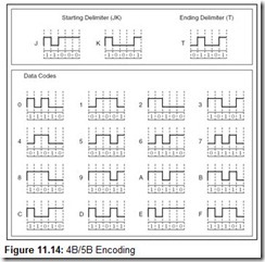
Note that the signal-carrying capacity of the cable grades shown in Table 11.1 is given in terms of megahertz. This is not the same as megabits. As we saw in Section 2.7, the number of bits carried at any given frequency is a function of the encoding method used in the network. Networks running below 100Mbps could easily afford to use Manchester coding, which requires two signal transitions for every bit transmitted. Networks running at 100Mbps and above use different encoding schemes, one of the most popular being the 4B/5B, 4 bits in 5 baud using NRZI signaling, as shown in Figure 11.14.
Baud is the unit of measure for the number of signal transitions supported by a transmission medium or transmission method over a medium. For networks other than the voice telephone network, the line speed is rated in hertz, but hertz and baud are equivalent with regard to digital signals. As you can see by Figure 11.14, if a network uses 4B/5B encoding, a signal-carrying capacity of 125MHz is required for the line to have a bit rate of 100Mbps.
Fiber Optic Cable
Optical fiber network media can carry signals faster and farther than either twisted pair or coaxial cable. Fiber optic cable is theoretically able to support frequencies in the terahertz range, but transmission speeds are more commonly in the range of about 2 gigahertz, carried over runs of 10 to 100 km (without repeaters). Optical cable consists of bundles of thin (1.5 to 125µm) glass or plastic strands surrounded by a protective plastic sheath. Although the underlying physics is quite different, you can think of a fiber optic strand as a conductor of light just as copper is a conductor of electricity. The cable is a type of “light guide” that routes the light from one end of the cable to the other. At the sending end, a light emitting diode or laser diode emits pulses of light that travel through the glass strand, much as water goes through a pipe. On the receiving end, photodetectors convert the light pulses into electrical signals for processing by electronic devices.
Optical fiber supports three different transmission modes depending on the type of fiber used. The types of fiber are shown in Figure 11.15. The narrowest fiber, single-mode fiber, conveys light at only one wavelength, typically 850, 1300, or 1500 nanometers. It allows the fastest data rates over the longest distances.
Multimode fiber can carry several different light wavelengths simultaneously through a larger fiber core. In multimode fiber, the laser light waves bounce off of the sides of the fiber core, causing greater attenuation than single-mode fiber. Not only do the light waves scatter, but they also collide with one another to some degree, causing further attenuation.
Multimode graded index fiber also supports multiple wavelengths concurrently, but it does so in a more controlled manner than regular multimode fiber. Multimode graded index fiber consists of concentric layers of plastic or glass, each with refractive properties that are optimized for carrying specific light wavelengths. Like regular multimode fiber, light travels in waves through multimode graded index optical fiber. But unlike multimode fiber, the waves are confined to the area of the optical fiber that is suitable to propagating its particular wavelength. Thus, the different wavelengths concurrently transmitted through the fiber do not interfere with each other.
The fiber optic medium offers many advantages over copper, the most obvious being its enormous signal-carrying capacity. It is also immune to EMI and RFI, making it ideal for deployment in industrial facilities. Fiber optic is small and lightweight, one fiber being capable of replacing hundreds of pairs of copper wires.
But optical cable is fragile and costly to purchase and install. Because of this, fiber is most often used as network backbone cable, which bears the traffic of hundreds or thousands of users. Backbone cable is like an interstate highway. Access to it is limited to specific entrance and exit points, but a large volume of traffic is carried at high speed. For a vehicle to get to its final destination, it has to exit the highway and perhaps drive through a residential street. The network equivalent of a residential street most often takes the form of twisted pair copper wire. This “residential street” copper wire is sometimes called horizontal cable, to differentiate it from backbone (vertical) cable. Undoubtedly, “fiber to the desktop” will eventually become a reality as costs decrease. At the same time, demand is steadily increasing for the integration of data voice and video over the same cable. With the deployment of these new technologies, network media probably will be stretched to their limits before the next generation of high-speed cabling is introduced.
11.6.2 Interface Cards
Transmission media are connected to clients, hosts, and other network devices through network interfaces. Because these interfaces are often implemented on removable circuit boards, they are commonly called network interface cards, or simply NICs. (Please don’t say “NIC card”!) A NIC usually embodies the lowest three layers of the OSI protocol stack. It forms the bridge between the physical components of the network and your system. NICs attach directly to a system’s main bus or dedicated I/O bus. They convert the parallel data passed on the system bus to the serial signals broadcast on a communications medium. NICs change the encoding of the data from binary to the Manchester or 4B/5B of the network (and vice versa). NICs also provide physical connections and negotiate permission to place signals on the network medium.
Every network card has a unique physical address burned into its circuits. This is called a Media Access Control (MAC) address, and it is 6 bytes long. The first 3 bytes are the manufacturer’s identification number, which is designated by the IEEE. The last 3 bytes are a unique identifier assigned to the NIC by the manufacturer. No two cards anywhere in the world should ever have the same MAC address. Network protocol layers map this physical MAC address to at least one logical address. The logical address is the name or address by which the node is known to other nodes on the network. It is possible for one computer (logical address) to have two or more NICs, but each NIC will have a distinct MAC address.
11.6.3 Repeaters
A small office LAN installation will have many NICs within a few feet of each other. In an office complex, however, NICs may be separated by hundreds of feet of cable. The longer the cable, the greater the signal attenuation. The effects of attenuation can be mitigated either by reducing transmission speed (usually an unacceptable option) or by adding repeaters to the network. Repeaters counteract attenuation by amplifying signals as they are passed through the physical cabling of the network. The number of repeaters required for any network depends on the distance over which the signal is transmitted, the medium used, and the signaling speed of the line. For example, high-frequency copper wire needs more repeaters per kilometer than optical cable operating at a comparable frequency.
Repeaters are part of the network medium. In theory, they are dumb devices functioning entirely without human intervention. As such, they would contain no network-addressable components. However, some repeaters now offer higher-level services to assist with network management and troubleshooting. Figure 11.16 is a representation of how a repeater regenerates an attenuated digital signal.
11.6.4 Hubs
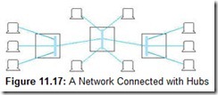
Repeaters are Physical layer devices having one input and one output port. Hubs are also Physical layer devices, but they can have many ports for input and output. They receive incoming packets from one or more locations and broadcast the packets to one or more devices on the network. Hubs allow computers to be joined to form network segments. The simplest hubs are nothing more than repeaters that connect various branches of a network. Physical network branches stuck together by hubs do not partition the network in any way; they are strictly Layer 1 devices and are not aware of a packet’s source or its destination. Every station on the network continues to compete for bandwidth with every other station on the network, regardless of the presence or absence of intervening hubs. Because hubs are Layer 1 devices, the physical medium must be the same on all ports of the hub. You can think of simple hubs as being nothing more than repeaters that provide multiple station access to the physical network. Figure 11.17 shows a network equipped with three hubs.
As hub architectures have evolved, many now have the ability to connect dissimilar physical media. Although such media interconnection is a Layer 2 function, manufacturers continue to call these devices “hubs.” Switching hubs and intelligent hubs are still further removed from the notion of a hub being a “Layer 1 device.” These sophisticated components not only connect dissimilar media, but also perform rudimentary routing and protocol conversion, which are all Layer 3 functions.
11.6.5 Switches
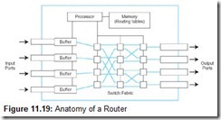
A switch is a Layer 2 device that creates a point-to-point connection between one of its input ports and one of its output ports. Although hubs and switches perform the same function, they differ in how they handle the data internally. Hubs broadcast the packets to all computers on the network and handle only one packet at a time. Switches, on the other hand, can handle multiple communications between the computers attached to them. If there were only two computers on the network, a hub and a switch would behave in exactly the same way. If more than two computers were trying to communicate on a network, a switch gives better performance because the full bandwidth of the network is available at both sides of the switch. Therefore, switches are preferred to hubs in most network installations. In Chapter 9 we introduced switches that connect processors to memories or processors to processors. Those switches are the same kind of switches we discuss here. Switches contain some number of buffered input ports, an equal number of output ports, a switching fabric (a combination of the switching units, the integrated circuits that they contain, and the programming that allows switching paths to be controlled) and digital hardware that interprets address information encoded on network frames as they arrive in the input buffers.
As with most of the network components we have been discussing, switches have been improved by adding addressability and management features. Most switches today can report on the amount and type of traffic that they are handling and can even filter out certain network packets based on user-supplied parameters. Because all switching functions are carried out in hardware, switches are the preferred devices for interconnecting high-performance network components.
11.6.6 Bridges and Gateways
The purpose of both bridges and gateways is to provide a link between two dissimilar network segments. Both can support different media (and network speeds), and they are both “store and forward” devices, holding an entire frame before sending it on. But that’s where their similarities end.
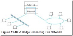
Bridges join two similar types of networks so they look like one network. With bridges, all computers on the network belong to the same subnet (the network consisting of all devices whose IP addresses have the same prefix). Bridges are relatively simple devices with functionality primarily at Layer 2. This means that they know nothing about protocols, but simply forward data depending on the destination address. Bridges can connect different media having different media access control protocols, but the protocol from the MAC layer through all higher layers in the OSI stack must be identical in both segments. This relationship is shown in Figure 11.18.
Each node connected to any particular bridge must have a unique address. (The MAC address is most often used.) The network administrator must program simple bridges with the addresses and segment numbers of each valid node on the network. The only data that is allowed to cross the bridge is data that is being sent to a valid address on the other side of the bridge. For large networks that change frequently (most networks), this continual reprogramming is tedious, time-consuming, and error-prone. Transparent bridges were invented to alleviate this problem. They are sophisticated devices that have the ability to learn the address of every device on each segment. Transparent bridges can also supply management information such as throughput reports. Such functionality implies that a bridge is not entirely a Layer 2 device. However, bridges still require identical Network layer protocols and identical interfaces to those protocols on both interconnected segments.
Figure 11.18 shows two different kinds of local area networks connected to each other through a bridge. This is typically how bridges are used. If, however, users on these LANs needed to connect to a system that uses a radically different protocol, for example a public switched telephone network or a host computer that uses a nonstandard proprietary protocol, then a gateway is required. A gateway is a point of entrance to another network. Gateways are full-featured computers that supply communications services spanning all seven OSI layers. Gateway system software converts protocols and character codes, and can provide encryption and decryption services. Because they do so much work in their software, gateways cannot provide the throughput of hardware-based bridges, but they make up for it by providing enormously more functionality. Gateways are often connected directly to switches and routers.
11.6.7 Routers and Routing
After gateways, routers are the next most complicated components in a network. They are, in fact, small special-purpose computers. A router is a device (or a piece of software) connected to at least two networks that determines the destination to which a packet should be forwarded. Routers are normally located at gateways. Operating correctly, routers make the network fast and responsive. Operating incorrectly, one faulty router can bring down the whole system. In this section, we reveal the inner workings of routers, and discuss the thorny problems that routers are called upon to solve.
Despite their complexity, routers are usually referred to as Layer 3 devices, because most of their work is done at the Network layer of the OSI Reference Model. However, most routers also provide some network monitoring, management, and troubleshooting services. Because routers are by definition Layer 3 devices, they can bridge different network media types (fiber to copper, for example) and connect different network protocols running at Layer 3 and below. Owing to their abilities, routers are sometimes referred to as “intermediate systems” or “gateways” in Internet standards literature. (When the first Internet standards were written, the word router hadn’t yet been coined.)
Routers are designed specifically to connect two networks together, typically a LAN to a WAN. They are complex devices because not only do they contain buffers and switching logic, but they also have enough memory and processing power to calculate the best way to send a packet to its destination. A conceptual model of the internals of a router is shown in Figure 11.19.
In large networks, routers find an approximate solution to a problem that is fundamentally NP-complete. An NP-complete problem is one in which its optimal solution is theoretically impossible within a time period that is short enough for that solution to be useful.
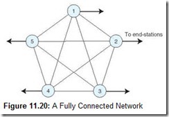
Consider the network shown in Figure 11.20. You may recognize this figure as a complete graph (K5). There are n(n – 1) / 2 edges in a complete graph containing n nodes. In our illustration, we have 5 nodes and 10 edges. The edges represent routes—or hops—between each of the nodes.
If Node 1 (Router 1) needs to send a packet to Node 2, it has the following choices of routes:
1 ® 2
three routes of two hops:
1 ® 3 ® 2 1 ® 4 ® 2 1 ® 5 ® 2
six routes of three hops:
1 ® 3 ® 4 ® 2    1 ® 3 ® 5 ® 2    1 ® 5 ® 4 ® 2
1 ® 4 ® 3 ® 2    1 ® 5 ® 3 ® 2    1 ® 4 ® 5 ® 2
six routes of four hops:
1 ® 3 ® 4 ® 5 ® 2    1 ® 4 ® 3 ® 5 ® 2    1 ® 5 ® 4 ® 3 ® 2
1 ® 3 ® 5 ® 4 ® 2    1 ® 4 ® 5 ® 3 ® 2    1 ® 5 ® 3 ® 4 ® 2
When Node 1 and Node 2 are not directly connected, the traffic between them must pass through at least one intermediate node. Considering all options, the number of possible routes is on the algorithmic order of N!. This problem is further complicated when costs or weights are applied to the routing paths. Worse yet, the weights can change depending on traffic flow. For example, if the connection between Nodes 1 and 2 were a tariffed high-latency (slow) line, we might be a whole lot better off using the 1 ® 4 ® 5 ® 3 ® 2 route. Clearly, in a real-world network, with hundreds of routers, the problem becomes enormous. If each router had to come up with the perfect outbound route for each incoming packet by considering all of the possibilities, the packets would never get where they were going quickly enough to make anyone happy.
Of course, in a very stable network with only a few nodes, it is possible to program each router so that it always uses the optimal route. This is called static routing, and it is feasible in networks where a large number of users in one location use a centralized host, or gateway, in another location. In the short term, this is an effective way to interconnect systems, but if a problem arises in one of the interconnecting links or routers, users are disconnected from the host. A human being must quickly respond to restore service. Static routing just isn’t a reasonable option for networks that change frequently. This is to say static routing isn’t an option for most networks. Conversely, static networks are predictable as the path (and thus the number of hops) a packet will take is always known and can be controlled. Static routing is also very stable, and it creates no routing protocol exchange traffic.
Dynamic routers automatically set up routes and respond to the changes in the network. These routers can also select an optimal route as well as a backup route should something happen to the route of choice. They do not change routing instructions, but instead allow for dynamic altering of routing tables.
Dynamic routers automatically explore their networks through information exchanges with other routers on the network. The information packets exchanged by the routers reveal their addresses and costs of getting from one point to another. Using this information, each router assembles a table of values in memory. This routing table is, in truth, a reachability list for every node on the network, plus some default values. Typically, each destination node is listed along with the neighboring, or next-hop, router to which it is connected.
When creating their tables, dynamic routers consider one of two metrics. They can use either the distance to travel between two nodes, or the condition of the network in terms of measured latency. The algorithms using the first metric are distance vector routing algorithms. Link state routing algorithms use the second metric.
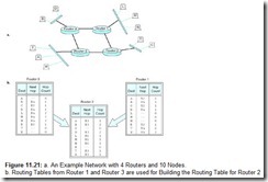
Distance vector routing is derived from a pair of similar algorithms invented in 1957 and 1962 known respectively as the Bellman-Ford and Ford-Fulkerson algorithms. The distance in distance vector routing is usually a measure of the number of nodes (hops) through which a packet must pass before reaching its destination, but any metric can be used. For example, suppose we have the network shown in Figure 11.21a. There are 4 routers and 10 nodes connected as indicated. If node B wants to send a packet to node L, there are two choices: One is B ® Router 4 ® Router 1 ® L, with one hop between Router 4 and Router 1. The other routing choice has three hops between the routers: B ® Router 4 ® Router 3 ® Router 2 ® Router 1 ® L. With distance vector routing, the objective is to always use the shortest route, so our B ® Router 4 ® Router 1 ® L route is the obvious choice.
In distance vector routing, every router needs to know the identities of each node connected to each router as well as the hop counts between them. To do this efficiently, routers exchange node and hop count information with their adjacent neighbors. For example, using the network shown in Figure 11.21a, Router 1 and Router 3 would have routing tables as shown in Figure 11.21b. These routing tables are then sent to Router 2. As shown in the figure, Router 2 selects the shortest path to any of the nodes considering all of the routes that are reported in the routing tables. The final routing table contains the addresses of nodes directly connected to Router 2 along with a list of destination nodes that are reachable through other routers and a hop count to those nodes. Notice that the hop counts in the final table for Router 2 are increased by 1 to account for the one hop between Router 2 and Router 1, and Router 2 and Router 3. A real routing table would also contain a default router address that would be used for nodes that are not directly connected to the network, such as stations on a remote LAN or Internet destinations, for example.
Distance vector routing is easy to implement, but it does have a few problems. For one thing, it can take a long time for the routing tables to stabilize (or converge) in a large network. Additionally, a considerable amount of traffic is placed on the network as the routing tables are updated. And third, obsolete routes can persist in the routing tables, causing misrouted or lost packets. This last problem is called the count-to-infinity problem.
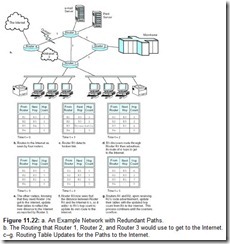
You can understand the count-to-infinity problem by studying the network shown in Figure 11.22a. Notice that there are redundant paths through the network. For example, if Router 3 goes offline, clients can still get to the mainframe and the Internet, but they won’t be able to print anything until Router 3 is again operational.
The paths from all of the routers to the Internet are shown in Figure 11.22b. We call the time that this snapshot was taken time t = 0. As you can see, Router 1 and Router 2 use Router 3 to get to the Internet. Sometime between t = 0 and t = 1, the link between Router 3 and Router 4 goes down, say someone unplugs the cable that connects these routers. At t = 1, Router 3 discovers this break, but has just received the routing table update from its neighbors, both of which advertise themselves as being able to get to the Internet in three hops. Router 3 then assumes that it can get to the Internet using one of these two routers and updates its table accordingly. It picks Router 1 as its next hop to the Internet then sends its routing table to Router 1 and Router 2 at t = 2. At t = 3, Router 1 and Router 2 receive Router 3’s updated hop count for getting to the Internet, so they add 1 to Router 3’s value (because they know that Router 3 is one hop away), and subsequently broadcast their tables. This cycle continues until all of the routers end up with a hop count of infinity, meaning that the registers that hold the hop count eventually overflow, crashing the whole network.
Two methods are commonly used to prevent this situation. One is to use a small value for infinity, facilitating early problem detection (before a register overflows), and the other is to somehow prevent short cycles like the one that happened in our example.
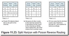
Sophisticated routers use a method called split horizon routing to keep short cycles out of the network. The idea is simple: No router will use a route given by its neighbor that includes itself in the route. (Similarly, the router could go ahead and use the self-referential route, but set the path value to infinity. This is called split horizon with poison reverse. The route is “poisoned” because it is marked as unreachable.) The routing table exchange for our example path to the Internet using split horizon routing would converge as shown in Figure 11.23. Of course, we still have the problem of larger cycles occurring. Say Router 1 points to Router 2, which points to Router 3, which points to Router 1. To some extent, this problem can be remedied if the routers exchange their tables only when a link needs to be updated. (These are called triggered updates.) Updates done in this manner cause fewer cycles in the routing graph and also reduce traffic on the network.
In large internetworks, hop counts can be a misleading metric, particularly when the network includes a variety of equipment and line speeds. For example, suppose a packet has two ways of getting somewhere. One path traverses six routers on a 100Mbps LAN, and the other traverses two routers on a 64Kbps leased line. Although the 100Mbps LAN could provide over ten times the throughput, the hop count metric would force traffic onto the slower leased line. If instead of counting hops we measure the actual line latency, we could prevent such anomalies. This is the idea behind link state routing.
As with distance vector routing, link state routing is a self-managing system. Each router discovers the speed of the lines between itself and its neighboring routers by periodically sending out Hello packets. At the instant it releases the packet, the router starts a timer. Each router that subsequently receives the packet immediately dispatches a reply. Once the initiator gets a reply, it stops its timer and divides the result by 2, giving the one-way time estimate for the link to the router that replied to the packet. Once all of the replies are received, the router assembles the timings into a table of link state values. This table is then broadcast to all other routers, except its adjacent neighbors. Nonadjacent routers then use this information to update all routes that include the sending router. Eventually, all routers within the routing domain end up with identical routing tables. Simply stated, after convergence takes place, a single snapshot of the network exists in the tables of each router. The routers then use this image to calculate the optimal path to every destination in its routing table.
In calculating optimal routes, each router is programmed to think of itself as the root node of a tree with every destination being an internal leaf node of the tree. Using this conceptualization, the router computes an optimal path to each destination using Dijkstra’s algorithm.[1] Once found, the router stores only the next hop along the path. It doesn’t store the entire path. The next (downstream) router should also have computed the same optimal path—or a better one by the time the packet gets there—so it would use the next link in the optimal path that was computed by its upstream predecessor. After Router 1 in Figure 11.22 has applied Dijkstra’s algorithm, it sees the network as shown in Figure 11.24.
Clearly, routers can retain only a finite amount of information. Once a network gets to a size where performance starts to degrade (usually this happens for reasons other than routing table saturation), the network must be split into subnetworks, or segments. In very large networks, hierarchical topologies that involve a combination of switching and routing technologies are employed to help keep the system manageable. The best network designers know when each technology is called for in the system design. The ultimate aim is to maximize throughput while keeping the network manageable and robust.
![]()
What Is a Firewall?
Virtually everyone in government, industry, and academia uses the Internet during the course of daily business. Yet, the Internet invites everyone on board—even those persons who would plunder or destroy a company’s computing resources. So how do you keep a network open enough for people to do their jobs but sufficiently secure to protect the assets of the business? The preferred solution to this problem is to place a firewall between the internal network and the Internet.
Firewalls get their name by drawing an analogy to the high brick walls that are sometimes placed between adjacent buildings. If a fire erupts in one of the buildings, the adjacent structure has some protection from becoming involved in the blaze. So it is with a network firewall: The internal users are partitioned from external users who may do harm to the internal network structure.
Firewalls come in many varieties. Two types that are most popular are router-based firewalls and host-based—or proxy server—firewalls. Both types are programmed with a rule base known as a policy. The firewall policy defines which network addresses can have access to which services. A good example of a policy involves file transfers. A firewall could be programmed to allow internal users (on the protected side of the network) to download files from the Internet. Users outside the protected network would be prohibited from downloading files from the internal network. The assumption is that data on the inside of the network may contain sensitive, private information. Any firewall can also be programmed with a list of forbidden addresses. (This is sometimes called a blacklist.) Blacklisted addresses often include the Web sites of groups disseminating objectionable material.
Both types of firewalls also distinguish between inbound and outbound traffic. This prevents the address spoofing that attempts to fool a firewall into thinking that a user is inside the network, when in fact the user is outside the network. If the firewall were fooled by a spoofed address, an external user would have free run of the internal network.
Both router-based firewalls and proxy servers have the ability to encrypt network traffic. Encryption is the process of scrambling a message using an algorithm and a key value so that the only device that can read the message is the device having the corresponding key. Key values are changed periodically, usually daily. This process happens automatically when firewalls are programmed with key exchange routines. Routers tend to use simpler encryption algorithms, usually based on simple bit shifts and logical ANDs using the message and the key value. (One such algorithm is the United States federal Data Encryption Standard [DES]. For more security the message is sometimes encrypted three times. This is called Triple-DES.)
As you might expect, proxy servers are slower and more prone to failure than router-based firewalls, but they also have many more features than router-based firewalls. First among these is their ability to act as an agent for users on the internal network (hence the name proxy server). These systems are usually equipped with two network cards; that is, they are dual homed. One network card connects to the internal network, and the other connects to the outside network. With this configuration, the server can completely mask the characteristics of the internal network from anyone on the outside. All that the external users can see is the address of the network interface that is connected to the outside.
Server-based firewalls can also maintain extensive network logs. Through these logs, security administrators can detect most invasion attempts by external evildoers. In some cases, logs can provide information regarding the source of a penetration attempt.
![]()
[1] For an explanation of Dijkstra’s algorithm, see Appendix A.
11.7 High-Capacity Digital Links
Now that you have an understanding of the physical components of data networks and the protocols that make them operate, we can venture into the domain of the global communications infrastructure. The sections that follow will introduce you to concepts and issues involved in building a network of digital pipes that is shared by data, voice, and video. Integrating these dissimilar traffic types has become possible only within the past decade, and it is still undergoing refinement. But it has come a long way from its beginnings.
11.7.1 The Digital Hierarchy
The notion of laying huge digital pipes came as an afterthought to dial tone service providers. Until the late 1960s, telephone services universally employed analog signals throughout their systems. High-capacity analog lines (trunk lines) connected toll centers located in cities around the world. Trunk lines, using a technique called frequency division multiplexing (FDM), carry several calls simultaneously over a single pair of copper wires. FDM can be compared to a radio receiver. You select any radio station that you want by turning a tuning dial. All of these signals can share the same communications medium because they exist at different frequencies. When FDM is used over long-distance telephone cables, each call is assigned its own frequency band, allowing a dozen or more calls to easily travel over the same conductor without interfering with one another.
There were a number of problems with the analog system, not the least of which was the matter of attenuation. To keep signals from fading away over the long haul, analog amplifiers were placed every few miles along the line. As the amplifiers boosted the voice signal, they also boosted the interference and background noise that was bound to leak into the wires along the way. The result was poor voice quality, which was accompanied by an annoying static crackle over very long distance connections.
During the 1960s, the Bell System began converting its trunk lines from analog to digital. Instead of using amplifiers to boost signals, digital carriers used repeaters to regenerate signals. Not only are repeaters much less expensive and more reliable than amplifiers, they reproduce only the signals that are supposed to be on the line. Background noise is not part of the signal, so it does not get regenerated and passed down the channel. Of course, because the human voice is an analog signal, it must be digitized before being sent over a digital carrier. The technique used for this conversion is called pulse-code modulation (PCM).
PCM relies on the fact that the highest frequency produced by a normal human voice is around 4000Hz. Therefore, if the voices of a telephone conversation are sampled 8000 times per second, the amplitude and frequency can be accurately rendered in digital form. This idea is shown in Figure 11.25. Figure 11.25a shows pulse amplitude modulation with evenly spaced (horizontal) quantization levels. Each quantization level can be encoded with a binary value. This configuration conveys as much information by each bit at the high end as the low end of the 4000Hz bandwidth. Yet the “information” produced by the human voice and detected by the human ear is not evenly spaced. It is instead bunched around the middle of the bandwidth. Because of this, a higher fidelity rendering of the human voice is produced when the quantization levels of PCM are similarly bunched around the middle of the band, as shown in Figure 11.25b. Thus, PCM carries information in a manner that reflects how it is produced and interpreted.
Through subjective tests, engineers from BellCore (the Bell System’s engineering unit, now called Telcordia) determined that when they used 127 quantization levels, the pulse-code modulation signal could not be distinguished from a pure analog signal. Therefore, the amplitude of the signal could be conveyed using only 7 bits for each sample. In the earliest PCM deployments, an eighth bit was added to the PCM sample for signaling and control purposes within the Bell System. Today, all 8 bits are used. A single stream of PCM signals produced by one voice connection requires a bandwidth of 64Kbps (8 bits x 8,000 samples/sec.). Digital Signal 0 (DS-0) is the signal rate of the 64Kbps PCM bit stream.
To form a transmission frame, a series of PCM signals from 24 different voice connections is placed on the line, with a control channel and framing bit forming a 125µs frame, as shown in Figure 11.26. This process is called time division multiplexing (TDM) because each connection gets roughly 1/24th of the 125µs frame. At 8000 samples per second per connection, the combination of the voice channels, signaling channel, and framing bit requires a total bandwidth of 1.544Mbps.
Europe and Japan use a larger frame size than the one that is used in North America. The European standard uses 32 channels, 2 of which are used for signaling and synchronization and 30 of which are used for voice signals. The total frame size is 256 bits and requires a bandwidth of 2.048Mbps.
The 1.544Mbps and 2.048Mbps line speeds (transmission speeds) are called T-1 and E-1, respectively, and they carry DS-1 signals. Just as 24 or 32 telephone conversations can be multiplexed to form one frame, the frames themselves can be multiplexed onto higher-speed links. Figure 11.27 shows how slower-speed tributary lines are multiplexed into high-speed trunk lines. The set of carrier speeds that results from these multiplexing levels is called the Plesiochronous Digital Hierarchy (PDH). The hierarchy is called plesiochronous (as opposed to synchronous) because each network element (such as a switch or multiplexer) has its own clock that it periodically synchronizes with the clocks above it in the hierarchy. (There is no separate timing signal placed on the carrier, as is the case with a true synchronous network.) The clocks at the topmost level of the hierarchy are extremely accurate and experience negligible drift. However, as the timing exchange signals propagate through the hierarchy, errors are introduced. And, of course, the deeper the hierarchy, the more likely it is that the signals will drift or slip before reaching the bottom.
The ultimate solution to the timing problems inherent in the PDH is to provide a single timing signal to all elements in the network. During the 1980s, BellCore and ANSI formulated standards for a synchronous optical network, SONET. It ultimately became the prevalent optical carrier system in North America. Because SONET was built around the 193-bit T-carrier frame size and European systems use a 256-bit frame, SONET was unsuitable for deployment in Europe. Instead, the Europeans adapted SONET to the E-carrier system, calling it the synchronous digital hierarchy, or SDH. Just as the basic signal of the T-carrier system is DS-1 at 1.544Mbps, the basic SONET signal is STS-1 (Synchronous Transport System 1) at 51.84Mbps. When an STS signal is passed over an optical carrier network, the signal is called OCx, where x is the carrier speed. The fundamental SDH signal is STM-1, which conveys signals at a rate of 155.52Mbps. The optical carrier hierarchy SONET along with SDH are shown in Table 11.2. Bit rates lower than those shown in the figure are transported using the T and E-carrier systems.
Table 11.2: North American (SONET) and European (SDH) Optical Carrier Systems
For long-distance transmission, T-3 and E-3 frames are converted to OC-1 and SDH-1 (and higher) carriers. Using SONET or SDH, however, eliminates the need for a stepped hierarchy as shown in Figure 11.27. Theoretically, 64 OC-3 carriers can be multiplexed directly onto an OC-192 carrier if there is a need to do so. This makes the network simpler to manage and reduces latency across the system.
The optical carrier system is suitable as a bearer service for ultra-fast WAN and Internet infrastructures. The problem has now become one of getting these high-capacity services available to homes and small businesses. “The last mile” of telephone wiring-the local loop-connects switching offices to their customers. Most of this local loop is low-bandwidth twisted-pair copper wire, poorly suited for multi-megabit data transport. But the situation is improving as local telephone companies continue to upgrade their existing lines, and competitive local exchange carriers run new (fiber optic) lines in areas where they expect such efforts to be profitable.
11.7.2 ISDN
The notion of delivering digital communications services directly to homes and businesses is hardly a new one. It dates back to the origins of digitized voice transmission. Three decades ago, however, the idea was a little before its time. It was 1972 when the ITU-T (then known as the CCITT) began working on a series of recommendations for an all-digital network that would carry voice, video, and data directly to the consumer. This network would have a common interface, accessible to anyone with the right equipment. Accordingly, this network was called the Integrated Services Digital Network (ISDN). The first of this series of recommendations was published in 1982 with subsequent additions and refinements appearing over the next decade.
ISDN was designed in strict compliance with the ISO Reference Model. Elements of ISDN span the entire seven-layer model, but most of the recommendations pertain to only Layers 1 through 3. These ISDN recommendations center on various network terminations and interfaces located at specific reference points in the ISDN model. The organization of this system is shown in Figure 11.28.
Network Termination 1 (NT-1) is the network termination located entirely on the consumer’s premises. NT-1 connects to the digital network through a T (for terminal) interface. NT-1 devices can support multiple ISDN channels and diverse digital devices. Some of these digital devices, such as alarm systems, are always open (turned on) to the network. As many as eight devices can be directly connected to a single ISDN NT-1 device. Devices that can be connected directly to an NT-1 termination are called TE-1, for Terminal Equipment Type-1.
Equipment that cannot be connected directly to an NT-1 port can attach to the digital network through an ISDN Terminal Adapter (TA). Such equipment is called Terminal Equipment Type-2 (TE-2) and the reference point between the TA and the TE-2 is called the R (for rate) reference point. TE-2 includes any type of equipment that cannot be connected directly to a digital line, such as a home computer that must get to the Internet through a modem. TAs attach to the network through the S (for system) reference point.
Network Termination 2 (NT-2) is an intelligent ISDN interface that provides Layer 1 through Layer 3 services. Equipment requiring high bit rates, such as automated private branch (telephone) exchange systems and LANs, connect directly to an ISDN NT-2 port. NT-2 devices see the ISDN network through the T reference point. For all practical purposes, the S and T interfaces are the same, so you will sometimes see them referred to as an S/T interface. NT-2 devices are called Channel Service Unit/Data Service Units or (CSU/DSUs).
An ISDN local loop service connects to the ISDN exchange office at the U (user) reference point. The ISDN exchange office contains digital switching equipment that is completely separate and different from the analog telephone equipment. Analog telephone systems set up and tear down switched circuits between two callers based on an in-band signal. Stated another way, when you place a call using an analog telephone, the routing information (the number of the station that you are calling) is encoded in the same frequency band that carries your voice. Tones at special frequencies or pulses generated through the dialing mechanism encode the routing information. ISDN, however, carries this information in a separate signaling channel that is multiplexed with the data channels of the ISDN frame.
ISDN supports two signaling rate structures, Basic and Primary. The connections that use the Basic and Primary rate lines are called Basic Rate Interface (BRI) and Primary Rate Interface (PRI). A Basic Rate Interface consists of two 64Kbps B-Channels and one 16Kbps D-Channel. These channels completely occupy two channels of a T-1 frame plus one-quarter of a third one, as shown in Figure 11.29. ISDN Primary Rate Interfaces occupy the entire T-1 frame, providing 23 64Kbps B-Channels and the entire 64Kbps D-Channel. B-Channels can be multiplexed to provide higher data rates, such as 128Kbps residential Internet service.
The D-Channel provides signaling and network management services for the traffic on the B-Channels. The connection management is effected using a protocol called System Signaling 7 (SS7), which is beyond the scope of this text. (See the References at the end of this chapter.)
Unfortunately, the ISDN committees were neither sufficiently farsighted nor sufficiently expeditious in publishing their recommendations. In the nearly two decades that it took to bring the first ISDN products to market, the bandwidth requirements of businesses and consumers had far outstripped ISDN’s ability to deliver. Simply put, ISDN provides too much bandwidth for voice, and far too little for data. So, except for a relatively small number of home Internet users, ISDN has become a technological orphan. But the importance of ISDN is that it forms a bridge to more advanced and versatile digital system known as Asynchronous Transfer Mode (ATM).
11.7.3 Asynchronous Transfer Mode
The traditional time division multiplexing typically used in voice communication does not make the best use of transmission bandwidth. As two people engage in a (polite) conversation, one party pauses for a second or two before the other party begins to speak. During these two seconds or so of “dead air,” 16,000 empty channel slots might be sent down the line. With time-division multiplexing, this bandwidth is wasted because the entire channel is reserved for the duration of the call, regardless of whether it is carrying information.
If we could capture these empty slots, they could be employed for carrying data, or even another conversation. To do this, however, we have to break each channel out into its own discrete unit, completely abandoning the idea of having 24 fixed channels occupying a fixed 125µs channel frame. This is one of the key ideas behind ATM. Each conversation and each data transmission consists of a sequence of discrete 53-byte cells that can be managed and routed individually to make optimal use of whatever bandwidth is available.
As we mentioned above, when the (then) CCITT finally completed the ISDN specification in 1988, virtually all of the stakeholders understood that the technology was very nearly obsolete before it was deployed. Work began almost immediately devising the next generation of high-speed digital carriers. The CCITT realized that the future of telecommunications lay in the convergence of voice, data, and real-time video traffic onto a single bearer service. These diverse services require a bandwidth of at least 150Mbps, far beyond the reach of the ISDN specification that the CCITT had just completed. The CCITT decided to call this next generation of digital services broadband ISDN, or B-ISDN, to distinguish it from the (narrowband) ISDN services it was to replace.
By design, B-ISDN is downwardly compatible with ISDN. It uses virtually the same reference model, which is shown in Figure 11.30. Asynchronous Transfer Mode (ATM), the preferred architecture for implementing B-ISDN, directly supports three transmission services: full-duplex 155.52Mbps, full-duplex 622.08Mbps, and an asymmetrical mode where the upstream (to the network) data rate is 155.52Mbps and the downstream (from the network) data rate is 622.08Mbps.
ATM can carry data, voice, or video traffic within the payload of its 53-byte cells. These small cells (or physical PDUs) allow relatively simple hardware devices to handle switching and routing. Routing paths are simplified through the use of virtual paths, which combine several virtual connections into a single manageable stream. Virtually any medium-twisted pair, coax, or optical fiber-can support ATM signals with speeds ranging from 44.736Mbps to 155Mbps.
Although the ITU-T didn’t originally see ATM as anything more than a wide-area bearer service, ATM is suitable for virtually any higher-layer protocol. ATM can carry various protocols at differing transmission speeds. With these ideas in mind, the ATM Forum, a consortium of network equipment vendors, has been working since the early 1990s to bring ATM to these private networks. ATM promises to be a great unifier, providing a single networking technology for all sizes and speeds of networks, including LANs, MANs, and WANs. Before ATM can achieve this kind of pervasiveness, however, its installation cost must be reduced substantially to be competitive with current technologies. Until the value of carrying data, voice, and video over one medium can be shown, ATM will have dominion only as a long-haul, high bit rate networking technology.
11.8 A Look at the Internet
In Section 11.3, we described how the Internet went from its beginnings as a closed military research network to the open worldwide communications infrastructure of today. But, unfortunately, gaining access to the Internet is not quite as simple as gaining access to a dial tone. Most individuals and businesses connect to the Internet through privately operated Internet service providers (ISPs). Each of these ISPs maintains a switching center called a point-of-presence (POP). Many ISPs have more than one POP. POPs are often known to Internet users through their domain names, usually ending in .com, .net, or .biz, or a country code such as .uk or .de. Some POPs are connected through high-speed lines (T-1 or higher) to regional POPs or other major intermediary POPs. Roughly speaking, the bottom-to-top hierarchy of connections is end systems (PCs and workstations) connected to local ISPs, which in turn are connected to regional ISPs, which are connected to national and international ISPs (often called National Backbone Providers, or NBPs). New branches can easily be added to this hierarchy, as can new tiers. The NBPs must themselves be interconnected, and this is done through network access points (NAPs), which are special switching centers used by regional ISPs to connect to other regional ISPs. In the United States, some local POPs concentrate their tributary traffic onto T-3 or OC-12 lines that carry traffic to one of a few NAPs. This ISP-POP-NAP hierarchy is shown in Figure 11.31. Each ISP and POP pays for its Internet usage according to the amount of traffic it puts on the lines through the NAPs. The more traffic, the more everyone pays. But much of the revenue has to be plowed back into equipment to maintain good customer service.
11.8.1 Ramping on to the Internet
Major Internet users, such as large corporations and government and academic institutions, are able to justify the cost of leasing direct high-capacity digital lines between their premises and their ISP. The cost of these leased lines is far beyond the reach of private individuals and small businesses, however. As a result, Internet users with modest bandwidth requirements typically use standard telephone lines to serve their telecommunications needs. Because standard telephone lines are built to carry analog (voice) signals, digital signals produced by a computer must first be converted, or modulated, from analog to digital form, before they are transmitted over the phone line. At the receiving end, they must be demodulated from analog to digital. A device called a modulator/demodulator, or modem, performs this signal conversion. Most home computers come equipped with built-in modems. These modems connect directly to the system’s I/O bus.
Traditional Dial-Up Lines and Modems
Voice-grade telephone lines are designed to carry signal frequencies in the range of 300Hz to 3300Hz, yielding a total bandwidth of 3000Hz. In 1924, information theorist Henry Nyquist showed that no signal can convey information at a rate faster than twice its frequency. Symbolically:
DataRatemax = 2 x (bandwidth) x log2 (number of signal levels) baud,
where baud is the signaling speed of the line.
So, mathematically speaking, a 3000Hz signal can transmit two-level (binary) data at a rate no faster than 6000 baud.
In 1948, Claude Shannon extended Nyquist’s work to consider the presence of noise on the line, using the line’s signal-to-noise ratio. In symbols:
The public switched telephone network (PSTN) typically has a signal-to-noise ratio of 30dB. From Shannon’s result, it follows that the maximum data rate of voice grade telephone lines is approximately 30,000bps, regardless of the number of signal levels used. Some modems push throughput to 56Kbps using data compression, but the compressed data still travels no faster than 30Kbps. (Ironically, because most modems use the ITU-T v42.bis compression standard, a Ziv-Lempel derivative, throughput can degrade radically when downloading a file that is already compressed, such as JPEG, GIF, or ZIP files. Recall from Chapter 7 that dictionary-based compression schemes can actually cause a file to expand if it contains insufficient redundancy, as is the case with a file that is already compressed.)
Modulating a digital signal onto an analog carrier means that some characteristic of the analog carrier signal is changed so that the signal can convey digital information. Varying the amplitude, varying the frequency, or varying the phase of the signal can produce analog modulation of a digital signal. These forms of modulation are shown in Figure 11.32. Figure 11.32a shows an unmodulated carrier signal, the frequency of which cannot exceed 3000Hz. Figure 11.32b shows that same carrier as it is modulated using changes in the amplitude (height) of the signal to transmit the ASCII character “K.” Figures 11.32c and 11.32d show this same bit pattern modulated using frequency modulation and phase change modulation. In Figure 11.32d, ones are distinguished from zeroes by shifting the phase of the signal by 180°. This modulation method is sometimes also called phase shift keying.
For all practical purposes, using simple amplitude, frequency, or 180° phase-change modulation limits throughput to about 2400bps. To get around this limit, modem makers vary two characteristics at a time instead of just one. One such modulation method, quadrature amplitude modulation (QAM), changes both the phase and the amplitude of the carrier signal. QAM uses two carrier signals that are 180° out of phase with each other. You can think of one of these signals as being a sine wave and the other as a cosine wave. We can modulate these two waves to create a set of Cartesian coordinates. The X,Y coordinates in this plane describe signal points that encode specified bit patterns. So a sine wave could be modulated for the Y-coordinate and the cosine wave for the X-coordinate. The sine and cosine waves would be added together to create a single analog wave that is easily transmitted across the line.
The set of signal points described on the Cartesian plane by modulating sine and cosine waves is called a signal constellation or signal lattice. Several bits can be encoded by each of the lattice points on the plane. Figure 11.33a shows a fictitious encoding of three bits per baud, where a 90° phase change or a change in the signal amplitude changes one bit pattern to another. The faster the modem, the more bits it transmits per baud and the denser its signal constellation becomes. Figure 11.33b shows a signal constellation for a trellis code modulation (TCM) modem. TCM is much like QAM except that a parity bit is added to each signal point, allowing for some forward error correction in the transmitted signal.
Modulating (and demodulating) a digital signal is only part of the job done by a modem. Modems are the bridge between the binary world of a host computer and the analog world of public telephone lines. They control the connection through a protocol exchange with the host system and the modem at the other end of the connection. Because there is essentially only one path for signal flow, analog transmission is necessarily serial and asynchronous. The oldest and most enduring of serial protocols is the IEEE RS-232-C standard. There are many others, including the newer EIA 232-D, RS-449, EIA 530, and ITU-T v24 and v28 protocols. All of these protocols are spelled out in excruciating detail in official documents published by their respective standards organizations, but the general idea behind asynchronous serial communication hasn’t changed since 1969 when the original RS-232-C standard was published.
RS-232-C officially consists of 24 named circuits over a standard 25-pin “D” connector. These circuits control the flow of data between the host and the modem, before the modem modulates the signal onto the transmission medium. In the standards literature, modems are referred to as data communications equipment (DCE), and the host computer is called data terminal equipment (DTE), both terms reflecting the technological era in which the original standards were written. Of the 24 circuits defined over the RS-232-C standard, only 8 of them are essential for most serial communications. Therefore, some standalone (external) modem manufacturers use a 9-pin “D” connector between the modem and host system. Pinouts for both 25-pin and 9-pin connectors are shown in Table 11.3.
Table 11.3: Pinouts and Circuit Designations for IEEE RS-232-C Serial Connectors
To place an outgoing call, a modem first opens the line (takes the phone “off hook”) and listens for a dial tone. If one is present, the modem asserts its Carrier Detect (CD) signal. Upon seeing this signal, the host supplies the number to be dialed, and the modem places the dialing signals onto the line, usually in the form of dialing tones. If a modem on the receiving end answers the call using the correct acknowledgement tones, both modems raise their Data Set Ready (DSR) signals. Once the initiating DTE sees the Data Set Ready signal, it asserts its Ready to Send (RTS) signal. When the modem notices that the host has raised RTS, it acknowledges with Clear to Send (CTS) and Data Carrier Detect (DCD).
Throughout the data transfer session, RTS, CTS, and DSR may be raised and lowered as data fills buffers and higher protocols perform error-checking and checkpoint procedures. Once the conversation is completed, the initiating host drops its RTS and CTS signals, causing the modem to place the line in the “on hook” state. When the modem at the other end notices that the connection has been terminated, it disconnects from the carrier and lowers its DCD signal to let its host know that the conversation has been terminated.
RS-232-C connections can be used for many different kinds of low speed data transfers. In the early days of microcomputers, virtually all printers had serial connections to their host systems, and these were RS-232 connections. Even today, null modems are sometimes used to transfer files from one system to another. A null modem is simply a pair of 9 or 25-pin connectors that are cabled as shown in Table 11.4. Using this configuration, two systems can be “faked” into thinking that there is a modem between them when there really isn’t. They can thus exchange a substantial amount of data without using disk, tape, or network resources.
Table 11.4: Pinouts for Null Modems
Although many home computers are equipped with internal modems, Internet service providers and other data service companies having large numbers of dial-up customers typically have modem banks consisting of dozens—or even hundreds—of modems. Inbound lines are configured so that if a particular circuit is busy, the connection “rolls” from one inbound line to the next until a free circuit is found. This connection switching takes place without the caller’s knowledge or active participation. Busy signals are sent only when all modems on all inbound lines are busy.
Digital Subscriber Lines
The 30Kbps limit that Shannon’s Law imposes on analog telephone modems is a formidable barrier to the promise of a boundless Internet world open to anyone who can afford a computer. Although long-distance telephone links have been fast and digital for decades, the local loop wires running from the telephone switching center to the consumer continue to use hundred-year-old analog technology. The “last mile” local loop can, in fact, span many miles, making it extremely expensive to bring the analog telephone service of yesterday into the digital world of the present.
Fortunately, the physical conductors in telephone wire are thick enough to support moderate-speed digital traffic for several miles without severe attenuation. Recognizing this, telecommunications groups have developed technologies to provide inexpensive digital services for residences and small businesses. Digital Subscriber Line (DSL) is one such technology that can coexist with plain old telephone service (POTS) on the same wire pair that carries the digital traffic. At present, most DSL services are available only to those customers whose premises connect with the central telephone switching office (CO) using less than 18,000 feet (5460 m) of copper cable. Of course, this is not the same thing as saying that a customer is within 18,000 feet of the CO, because the route taken by the service cable is rarely a straight line.
Traditional analog telephone service, POTS, terminates local loop service at a frame, or switching center, at the CO. From the switching center, a dedicated circuit is established through another switching center, perhaps onto a long-distance trunk line, or perhaps directly out of the same switching center back into the same local loop. All of this circuit switching takes place based on the analog characteristics of the connection.
As explained in our discussion of ISDN, the analog CO configuration is incompatible with digital technology. The digital equivalent of these analog telephone switches is a DSL access multiplexer (DSLAM). A DSLAM combines DSL traffic from multiple customer lines onto switched Ethernet, T-1/E-1, T-3/E-3, or ATM bearers for access to the Internet or other digital services. Some DSLAMs can also connect to the POTS switching frame, providing voice along with digital service.
At the customer’s premises, some DSLs require a splitter to separate voice from digital traffic. The digital signals terminate at a coder/decoder device, often called a DSL modem.
There are two different—and incompatible—modulation methods used by DSL: Carrierless Amplitude Phase (CAP) and Discrete MultiTone Service (DMT). CAP is the older and simpler of the two technologies, but DMT is the ANSI standard for DSL.
CAP uses three frequency ranges, 0 to 4KHz for voice, 25KHz to 160KHz for “upstream” traffic (such as sending a command through a browser asking to see a particular Web page), and 240KHz to 1.5MHz for “downstream” traffic (delivering the requested Web page). This imbalanced access method is called Asymmetric Digital Subscriber Line (ADSL). Because most Web sessions involve enormously more downstream traffic than upstream traffic, ADSL is quite suitable for home and small business Internet access.
Of course, with the fixed channel sizes of CAP, the user is locked in to an upstream bandwidth of 135KHz. This may not be ideal for someone who does a great deal of uploading, or desires remote connection to a LAN. In these situations, DMT DSL may offer better performance. DMT splits a 1MHz frequency bandwidth into 256 4KHz channels, called tones. These channels can be configured in any way that suits both the customer and the provider. For example, DMT could easily accommodate a customer who needs 192 4KHz (768KHz) upload channels and only 64 4KHz (256KHz) download channels. Although this kind of service is possible, DMT more often uses its flexibility to adapt to fluctuations in line quality. When DMT equipment detects excessive crosstalk or excessive attenuation on one of its channels, it stops using that channel until the situation is remedied. Although the bit rate of the line decreases after such measures are taken, actual throughput improves because a defective channel can cause many retransmissions, usually reducing the actual throughput by a factor much greater than would be caused by the loss of one or two 4KHz channels.
DSL is by no means limited to residential use. Higher-capacity DSL technologies are available over commercial T-1/E-1, T-3/E-3, and ATM services. Quite a few DSL technologies have emerged during the late 1990s, with more sure to follow. There is no consensus of opinion as to which one is “best,” and it is likely that the market will shake out only a few survivors within the next decade or so. To help you find your way through the confusion, we have provided a short glossary of a few popular DSL technologies in Table 11.5 for your reference.
Table 11.5: A DSL Vocabulary List
11.8.2 Ramping up the Internet
The analog local loop is only one of the problems facing the Internet today. Another much more serious problem is that of backbone router congestion. With upwards of 50,000 routers situated along the various backbone networks in the United States alone, routing table updates contribute substantially to the traffic along the backbones. It also requires a significant amount of time for the routing tables to converge. Obsolete routes can persist long enough to impede traffic, causing even more congestion as the system tries to resolve the error. Greater problems develop when a router malfunctions, broadcasting erroneous routes (or good routes that it subsequently cancels) to the entire backbone system. This is known as the router instability problem and it is an area of continuing research.
Surely, once IPv6 is adopted universally some of these problems will go away, because the routing tables ought to get smaller (assuming Aggregatable Global Unicast Addresses are used). But difficulties remain with millions of route advertisements happening each day, and the physical limitations of trying to get tens of thousands of routing tables to agree on what the network looks like at any instant. Ultimately, for backbones to keep pace with demand, deeper analyses are required. The outcome of this work may give rise to a new generation of routing protocols. One thing is certain: Simply giving the Internet more bandwidth offers little promise for making it any faster in the long-term. It has to get smarter.
Chapter Summary
This chapter has presented an overview of the network components and protocols that are used in building data communications systems. Each network component—each network process—carries out a task at some level within a layered protocol stack. Network engineers use layers of the OSI Reference Model to describe the roles and responsibilities of all network components. When a computer is engaged in communications with another computer, each layer of the protocol stack it is running converses with a corresponding layer running on the remote system. Protocol layers interface with their adjacent layers using service access points.
Most Internet applications rely on TCP/IP, which is by far the most widely deployed data communications protocol. Although often referred to as TCP/IP, this combination is actually two protocols. TCP provides a means for setting up a reliable communications stream on top of the unreliable IP. Version 4 of its IP component is constrained by its 32-bit address fields. Version 6 of IP will solve this problem because its address fields are 128 bits wide. With these larger address fields, routing could be a formidable task. With this in mind, the IETF has devised a hierarchical address scheme, the Aggregatable Global Unicast Address Format, which makes routing of packets both easier and faster.
We have described a number of components common to most data communications networks. The most important of these components are the physical media and the routers. Physical media must be chosen with consideration to the anticipated load and the distance to be covered. Physical media can be extended with repeaters when necessary. Routers are complex devices that monitor the state of the network. Their programming allows them to select nearly optimal paths for network traffic.
The public switched telephone network continues to be the Internet “on ramp” for home and small business users. Unfortunately, the circuits connecting customers with telephone switching centers are analog, carrying at most 30,000bps. Offering some relief to this situation, ISDN and DSL are two digital bearer services available to many homes and small businesses.
But the public switched telephone network is only one of the impediments to the growth of the Internet. The other is the problem of backbone router congestion. As the Internet continues its exponential growth as a vehicle for commerce, routing problems will grow proportionately. The solution to these problems may ultimately reside in rethinking the architecture and some of the assumptions that form the foundation of the Internet as we know it today.
Review of Essential Terms and Concepts
-
How is the organization of a polled network different from that of an internetwork?
-
What protocol device was the key to the robustness of DARPAnet?
-
Who establishes standards for the Internet?
-
What is the formal name given to Internet standards?
-
Which layer of the ISO/OSI Reference Model takes care of negotiating frame size and transmission speed?
-
If a communications session were to employ encryption or compression, which layer of the ISO/OSI Reference Model would perform this service?
-
According to the IPv4 format given in Section 11.5.1, what bit positions does the IP Protocol Number occupy? What is the purpose of this field?
-
Why have certain types of IP addresses become scarce?
-
Explain the general purpose of the TCP protocol.
-
How does IPv6 improve upon IPv4?
-
What is the difference between guided and unguided data transmission media? List some examples of each.
-
What determines the quality of a transmission medium? What metric is used?
-
What are the principal causes of attenuation? What can help reduce it?
-
What is the difference between the baud rate and the bit rate of a line?
-
What are the three types of fiber optic cable? Which of these can transmit signals the fastest?
-
Where does one find a MAC address? How many bytes are in a MAC address?
-
Briefly describe how repeaters, hubs, switches, and routers differ from one another.
-
What is the difference between a bridge and a gateway? Which one is faster and why?
-
When is it not a very good idea to use static routing?
-
Give two important ways in which link state routing differs from distance vector routing.
-
What are the three main problems that arise from distance vector routing?
-
In what ways does a firewall provide security?
-
What is pulse code modulation?
-
What is time division multiplexing?
-
In what ways does the PDH differ from SONET/SDH?
-
What went wrong with ISDN?
-
What is the chief benefit offered by ATM?
-
What is ATM’s principal limitation?
-
How does phase change modulation work?
-
How is trellis code modulation distinguished from quadrature amplitude modulation?
-
What are the two types of DSL? Which one is the ANSI standard?
-
Describe the router instability problem.
Exercises
-
In what way is the traffic of an early business computer network different from that of an early scientific-academic network? Is there such a distinction between these two types of systems today?
-
Why is the ISO/OSI protocol stack called a reference model? Do you think this will always be the case?
-
How is a Network layer protocol different from a Transport layer protocol?
-
Internet protocol standards are devised through the efforts of thousands of people all over the world-regardless of their having any particular background in data communications. On the other hand, proprietary protocols are created by a much smaller group of people, all of whom are directly or indirectly working for the same employer.
-
What advantages and disadvantages do you think are offered by each approach? Which would produce a better product? Which would produce a product more quickly?
-
Why do you think that the IETF approach has achieved ascendancy over the proprietary approach?
-
-
Hints and Answers In our description of the Window field in the TCP header, we said:
Notice that if the receiver’s application is running very slowly, say it’s pulling data one or two bytes at a time from its buffer, the TCP process running at the receiver should wait until the application buffer is empty enough to justify sending another segment.
What is the “justification” for sending another segment?
-
The OSI protocol stack includes Session and Presentation layers in addition to its Application layer. TCP/IP applications, such as Telnet and FTP, have no such separate layers defined. Do you think that such a separation should be made? Give some advantages and disadvantages of incorporating the OSI approach into TCP/IP.
-
Why is the length of a TCP segment limited to 65,515 bytes?
-
Why does the IETF use the word octet instead of byte? Do you think that this practice should continue?
-
Hints and Answers Into which class of networks do the following IP addresses fall?
-
Hints and Answers 180.265.14.3
-
Hints and Answers 218.193.149.222
-
Hints and Answers 92.146.292.7
-
-
Into which class of networks do the following IP addresses fall?
-
223.52.176.62
-
127.255.255.2
-
191.57.229.163
-
-
A station running TCP/IP needs to transfer a file to a host. The file contains 1024 bytes. How many bytes, including all of the TCP/IP overhead, would be sent, assuming a payload size of 128 bytes and that both systems are running IPv4? (Also assume that the three-way handshake and window size negotiation have been completed and that no errors occur during transmission.)
-
Hints and Answers What is the protocol overhead (stated as a percentage)?
-
Hints and Answers Perform the same calculation, this time assuming both clients are using IPv6.
-
-
A station running TCP/IP needs to transfer a file to a host. The file contains 2048 bytes. How many bytes, including all of the TCP/IP overhead, would be sent, assuming a payload size of 512 bytes and that both systems are running IPv4? (Also assume that the three-way handshake and window size negotiation have been completed and that no errors occur during transmission.)
-
What is the protocol overhead (stated as a percentage)?
-
Perform the same calculation, this time assuming both clients are using IPv6.
-
-
Hints and Answers Two stations running TCP/IP are engaged in transferring a file. This file is 100KB long, the payload size is 100 bytes, and the negotiated window size is 300 bytes. The sender receives an ACK 1500 from the receiver.
-
Hints and Answers Which bytes will be sent next?
-
Hints and Answers What is the last byte number that can be sent without an ACK being sent by the receiver?
-
-
Two stations running TCP/IP are engaged in transferring a file. This file is 10KB long, the payload size is 100 bytes, and the negotiated window size is 2000 bytes. The sender receives an ACK 900 from the receiver.
-
Which bytes will be sent next?
-
What is the last byte number that can be sent without an ACK being sent by the receiver?
-
-
What problems would present themselves if TCP did not allow senders and receivers to negotiate a timeout window?
-
IP is a connectionless protocol, whereas TCP is connection-oriented. How can these two protocols coexist in the same protocol stack?
-
Section 11.6.1 states that when using 4B/5B encoding, a signal-carrying capacity of 125MHz is required for a transmission medium to have a bit rate of 100Mbps.
-
What signal-carrying capacity would be required if Manchester coding were used instead?
-
What signal-carrying capacity would be required if modified frequency modulation (MFM) coding were used, assuming that the occurrence of a 0 or a 1 are equally likely events?
(Manchester and MFM coding are explained in Chapter 2.)
-
-
-
The signal power for a particular class of network wiring is 8733.26dB and the noise rating at that particular signal strength at 100MHz is 41.8dB. Find the signal-to-noise ratio for this conductor.
-
Suppose the noise rating for the network wiring in Part a is 9.5 dB and the noise rating is 36.9 dB when a 200MHz signal is transmitted. What is the signal strength?
-
-
-
The signal power for a particular class of network wiring is 2898dB and the noise rating at that particular signal strength at 100MHz is 40dB. Find the signal-to-noise ratio for this conductor.
-
Suppose the noise rating for the network wiring in Part a is 0.32 dB and the noise rating is 35 dB when a 200MHz signal is transmitted. What is the signal strength?
-
-
How big is a physical PDU? The answer to this question determines the number of simultaneous transmissions for many network architectures.
If a signal propagates through copper wire at the rate of 2 x 10⁸ meters per second, then on a carrier running at 10Mbps the length of each bit pulse is given by:
If a data frame is 512 bits long, then the entire frame occupies:
(Length of one bit) x (Frame size) = 20 x 512 = 10,240 meters.
-
How big is a 1024-bit packet if the network runs at 100Mbps?
-
How big is it if the network speed is increased to 155Mbps?
-
At 100Mbps, how much time elapses as one of these frames passes a particular point in the network?
-
-
It looks like the 4B/5B bit cells in Figure 11.14 are fairly small. How long, in reality, is such a bit cell on a 125MHz line? (Use the constants and formulas from the previous question.)
-
With reference to Figure 11.21, suppose Router 4 derives its routing table from the routing tables of Router 1 and Router 3. Complete the routing table for Router 4 using the same format as the routing table of the other three routers.
-
Because trellis code and other phase-change modulation techniques have been used to increase the signal-carrying capacity of common telephone lines, couldn’t we also do the same thing with digital lines?
-
In Section 11.8.1 we state, using Shannon’s law, that the maximum data rate for a standard analog telephone line is approximately 30,000 bps with a signal-to-noise ratio of 30dB. The ratio of signal to noise is 1000, because the signal-to-noise ratio is 10 log10 signal dB / noise dB, as explained in Section 11.6.1.
If a binary signal is sent over a 10Khz channel whose signal-to-noise ratio is 20dB, what is the maximum achievable data rate?
-
Using the same idea as in the previous question, suppose a channel has an intended capacity of 10Mbps with a bandwidth of 4MHz. What is the minimum signal-to-noise ratio (in dB) that the channel must have in order for it to be possible to achieve this data rate?
-
Construct a timing diagram to illustrate how two modems establish a connection using the RS-232 protocol described in the text.
-
The North American TDM DS-0 frame takes 125µs to pass one point on the line. How many milliseconds does it take for the European equivalent to pass a point on the line?
-
Figure 11.33b. shows a TCM constellation. Devise a code of bit strings that could be used for this constellation.
[Hint: The 32 signal points encode bit strings that are 4 bits long. The fifth bit is used for parity. Either even or odd parity may be used for this exercise.]
-
Devise a trellis code modulation constellation and encoding scheme that will encode 4 bits per baud (including the parity bit).
