SIMULATION AND CONTROL
Most control system designs rely on modeling the system to be controlled, allowing simulation studies to determine control strategies and optimum system parameters. These studies also allow complex what-if scenarios to be viewed, which may be difficult on the real system. However, it must always be borne in mind that any simulation results obtained are only as good as the model of the process. This does not mean that every effort should be made to get the model as realistic as possible, just that it should be sufficiently representative.
A simulation is the execution of a process or system model in a program that gives information about what is being investigated. The model consists of events, activated at certain points in time, that affect the overall state of the process or system. Computer simulation is a fast and flexible tool for generating models, either for current systems where modifications are planned or for completely new systems. Running the simulation predicts the effect of changing system parameters, provides information on the sensitivity of the process or system, and helps to identify an optimum solution for specific operating conditions.
The most important topics in modeling and simulation are:
1. Discrete event simulation is applicable to systems whose state changes abruptly in response to some event in the environment, examples being service facilities such as queues at printers and factory production lines;
2. Modeling of real-time systems is used to define requirements and high-level software design before
the implementation stage is attempted;
3. Continuous time simulation is used to compute the evolution in time of physical variables such as speed, temperature, voltage, level, position and so on for systems such as robots, chemical reactors, electric motors, and aircraft;
4. Rapid prototyping of control systems involves moving from the design of a controller to its implementation as a prototype.
In this section, the manufacturing process is selected as a representative process control and the computer control system as a representative system control the purposes of this discussion.
Industrial process simulation
In manufacturing processes, modeling and simulation can ensure the best balance of all constraints in designing, developing, producing, and supporting products. Cost, time compression, customer demands, and lifecycle responsibility will all be part of an equation balanced by captured knowledge, online analyses, and human decision-making. Modeling and simulation tools (to be discussed in the next section) can support best practice from concept creation through product retirement and disposal, and operation of the tools will be transparent to the user. Modeling and simulation activities in the manufacturing process can be divided into five functional elements, as given below.
(1) Material processing
Material processing involves all activities associated with the conversion of raw materials and stock to either a finished form or readiness for assembly.
Enterprise process modeling and simulation environments provide the integrated functionality to ensure the best material or product is produced at the lowest cost. The models include new, reused, and recycled materials to eliminate redundancy. An open, shared industrial knowledge base and model library are required to provide ready access to material properties data using standard forms of information representation (scaleable plug-and-play models), the means for validating models before use, a fundamental science-based understanding of material properties to processes, standard, validated time and cost models and supporting estimating tools for the full range of processes.
Material processing includes four general categories of process, which have a related type of modeling and simulation:
(a) Preparation and creation processes such as synthesis, crystal-growing, mixing, alloying, distilling, casting, pressing, blending, reacting, and molding;
(b) Treatment processes such as coating, plating, painting, and thermal and chemical conditioning;
(c) Forming processes for metals, plastics, composites, and other materials, including bending, extruding, folding, rolling, shearing, stamping;
(d) Removal and addition processes such as milling, drilling, routing, turning, cutting, sanding, trimming, etching, sputtering, vapor deposition, solid freeform fabrication, and ion implantation.
(2) Assemblies, disassembly, and reassembly
This functional element includes processes associated with joining, fastening, soldering, and integration of higher-level packages as required to complete a deliverable product (e.g., electronic packages); it also includes assembly sequencing, error correction and exception handling, disassembly and reassembly, which are maintenance and support issues.
Assembly modeling is well-developed for rigid bodies and tolerance stack-up in limited applications. Rapidly maturing computer-aided design and manufacturing technologies, coupled with advanced modeling and simulation techniques, offer the potential to optimize assembly processes for speed, efficiency, and ease of human interaction. Assembly models will integrate seamlessly with master product and factory operations models to provide all relevant data to drive and control each step of the design and manufacturing process, including tolerance stack-ups, assembly sequences, ergonomics issues, quality, and production rate to support part-to-part assembly, disassembly, and reassembly.
The product assembly model will be a dynamic, living model, adapting in response to changes in requirements and promulgating those changes to all affected elements of the assembly operation including process control, equipment configuration, and product measurement requirements.
(3) Qualities, test, and evaluation
This element includes designs for quality, in-process quality, all inspection and certification processes, such as dimensional, environmental, and chemical and physical property evaluation based on requirements and standards, and diagnostics as well as troubleshooting.
Modeling, simulation, and statistical methods are used to establish control models to which processes should conform. Process characterization, gives models which define the impact of different parameters on product quality. These models are used as a baseline for establishing and maintaining in-control processes. In general, the physics behind these techniques (e.g., radiological testing, ultrasonic evaluation, tomography, and tensile testing) should be well understood. However, many of the interactions are treated probabilistically and, even though models of the fundamental interactions exist, in most cases empirical methods are used instead. Although the method needs to be improved, at present the best way to find out whether a part has a flaw is to test samples. “Models” are used in setting up these experiments, but many times the models reside only in the brains of the experts who support the evaluations.
(4) Packaging
This element includes all final packaging processes, such as wrapping, stamping and marking, palletizing, and packing.
Modeling and simulation are critical for designing packaging that protects products. Logistic models and part tracking systems help us to ensure correct packaging and labeling. Applications range from the proper wrapping for chemical, food, and paper products to shipping containers that protect military hardware and munitions from accidental detonation.
Future process and product modeling and simulation systems will enable packaging designs and processes to be fully integrated into all aspects of the design-to-manufacturing process, and will provide needed functionality at minimum cost, and environmental impact, with no nonvalue-added operations. They will enable designers to optimize packaging designs and supporting processes, to give enhanced product value and performance, as well as for protection, preservation, and handling attributes.
(5) Remanufacture
This includes all design, manufacture, and support processes that support return and reprocessing of products on completion of their original intended use.
Manufacturers can reuse, recycle, and remanufacture products and materials to minimize material and energy consumption, and to maximize the total performance of manufacturing operations. Advanced modeling and simulation capabilities will enable manufacturers to explore and to analyze remanufacturing options to optimize the total product realization process and product and process life cycles for efficiency, cost-effectiveness, profitability, and environmental sensitivity.
Products will be designed from inception for remanufacture and reuse, either at the whole product, or the component or constituent material level. In some cases, ownership of a product may remain with the vendor (not unlike a lease), and the products may be repeatedly upgraded, maintained, and refurbished to extend their lives and add new capabilities.
Industrial system simulation
Modeling and simulation activities in computer control systems could be improved if the following technical issues are taken into account.
(1) Modeling purpose and simulation accuracy
One well-known challenge in modeling is to be able to identify the accuracy that is for a given purpose. Consider, for example, the implementation of a data-flow over two processors and a serial network. A huge span of modeling detail is possible, ranging from a simple delay over discrete-event resource management models (e.g., processor and communication scheduling) to low-level behavioral models. The mapping of these details between models and real computer networks will change the timing behavior of the functions due to effects such as delays and jitter. Some reflections related to this are as follows:
(a) The introduction of application-level effects, such as delays, jitter, and data loss, into a control design could be an appropriate abstraction for control engineering purposes. The mapping to the actual computer system may be nontrivial. For example, delays and jitter can be caused by various combinations of execution, communication, interference, and blocking. More accurate computer system models will be required to compare alternative designs (architectures), and to provide estimations of the system behavior. In addition, modeling is a sort of prototyping, and as such important in the design process.
(b) It is interesting that the underlying model of the computer control system could contain more
or less detail, given the right abstraction. For example, if a fairly detailed computer area network (CAN) model has been developed, it could still be used in the context of control system simulation given that it is sufficiently efficient to simulate and that its complexity can be masked off.
(c) It is obvious that models of a computer control system need to reflect the real system. In the early stages, architecture only exists on the drawing board. As the design proceeds, more and more details will be available; consequently, the models used for analysis must be updated accordingly.
(d) To achieve accuracy, close cooperation between software and hardware developers is necessary,
and is required at every stage during the system development.
(2) Global synchronization and node tasking
Both synchronous and asynchronous systems exist; industrially asynchronous systems predominate but this may change with the introduction of newer safety-critical applications such as steer-by-wire in cars, because of the advantages inherent in distributed systems based on a global clock.
Under the microscope, communication circuits are typically hard-synchronized, as is necessary to be able to receive bits and arbitrate properly. In a system with low-level synchronization, and/or synchronized clocks, the synchronization could fail in different ways. For asynchronous systems, it could be of interest to incorporate clock drift. Given different clocks with different speeds, this will affect all durations within each node. A conventional way of expressing duration is simply by a time value; in this case the values could possibly be scaled during the simulation set-up. All the above- mentioned behaviors could be interesting to model and simulate.
The most essential characteristic of a distributed computer system is undoubtedly its communication. In early design stages, the distributed and communication aspects are often targeted first; but then node scheduling also becomes interesting and is, therefore, of high rele- vance. It is very common that many activities coexist on nodes. Typically they have different timing requirements and may also be safety-critical. The scheduling on the nodes affects the distributed system by causing local delays that can influence overall behavior.
When developing a distributed control system, the functions and elements thereof need to be allocated to the nodes. This principally means that an implementation-independent functional design needs to be enhanced with new “system” functions, which for example (1) perform communication between parts of the control system, now residing on different nodes; (2) perform scheduling of the computer system processors and networks; (3) perform additional error-detection and handling to cater for new failure modes (e.g., broken network, temporary node failure, etc.).
A node is composed of application activities, system software including a real-time kernel, low-level I/O drivers, and hardware functions including the communication interface.
(a) The node task model
This needs to include the following: (i) a definition of tasks, their triggers, and execution times for execution units; (ii) a definition of the interactions between tasks in terms of scheduling, inter-task communication, and resource sharing; (iii) a definition of the real-time kernel and other system software with respect to execution time, blocking, and so on. Some issues in the further development include the types of inter-task communication and synchronization that should be supported (e.g., signals, mailboxes, semaphores.) and whether, and to what extent, there is a need to consider hierarchical and hybrid scheduling (e.g., including both the processor’s interrupt and real-time kernel scheduling levels).
(b) The functional model
The functional model used in conventional control design should be reusable within the combined- function computer models. This implies that it should be possible to adapt or refine the functional models to incorporate a node-level tasking model.
(c) Communication models
The types of communication protocols are determined by the area under consideration. Nevertheless, a number are currently being developed with a view to future embedded control systems. The CAN network is currently a default standard, but there is also an interest in including the following: (i) time- triggered computer area networks, which refers to CAN systems designed to incorporate clock synchronization suitable for distributed control applications; this rests on the potential of the recent ISO revision of CAN to more easily implement clock synchronization; (ii) properties reflecting state- of-art fault-tolerant protocols such as the time-triggered protocol. The fault-tolerance mechanisms of these protocols, such as membership management and atomic broadcasts, then need to be appropri- ately modeled.
It is often the case that parts of the protocols are realized in software, for example, dealing with message fragmentation, certain error detection, and potential retransmissions. In this case both the execution of the protocol and the scheduling need to be modeled. The semantics of the communication and in particular of buffers is another important aspect; compare, for example, overwriting and unconsuming semantics versus different types of buffering. Whether this is blocking or not from the point of view of the sender and receiver is also related to its semantics.
Another issue is which “low-level” features of communication controllers need to be taken into account. Compare, for example, the associative filtering capability of CAN controllers, and their internal sorting of message buffers scheduled for transmission (relates back to hierarchical scheduling).
796 CHAPTER 19 Industrial control system simulation routines
(d) Fault models
The use of fault models is essential for the design of dependable systems. The models of interest are very application-specific, but generic fault models and their implementation are of great interest. There are a number of studies available on fault models dealing with transient and permanent hardware faults, and to some extent also categorizing design faults. As always, there is also the issue of insertion in the form of a fault, an error, or a failure. Consequently, this is a prioritized topic for further work.
(3) System development and tool implementation
While developing distributed control systems, it would be advantageous to have a simulation toolbox or library in which the user can build the system based on prebuilt modules to define things such as the network protocols and the scheduling algorithms. With such a tool, the user could focus on the application details instead. This is possible, since components are standardized across applications and are well defined. In the same way as a programmer works on a certain level of abstraction, at which the hardware and operating system details are hidden by the compiler, the simulation tool should give the user a high level of abstraction to develop the application. Such a tool would enforce a boundary between the application and the rest of the system which would speed up the development process, and gives the developers extra flexibility.
It is clear that the implementation of hybrid systems (such as those combining discrete-event with continuous-time) that we are aiming to model requires a thorough knowledge of the simulation tool. Co-simulation of hybrid systems requires the simulation engine to handle both time-driven and event- triggered parts. The former includes sampled subsystems as well as continuous-time subsystems, handled by a numerical integration algorithm that can be based on a fixed or varying step size. The latter may involve state machines and other forms of event-triggered logic. Some aspects that need consideration for tool implementation are as follows:
(a) If events are used in the computer system model these must be detected by the simulation engine.
How is the event-detection mechanism implemented in the simulation tool?
(b) At which points are the actions of a state flow system carried out?
(c) How can actions be defined to be atomic (carried out during one simulation step)?
(d) How can preemption of simulation be implemented, including temporary blocking to model the effects of computer system scheduling?
Industrial control simulation
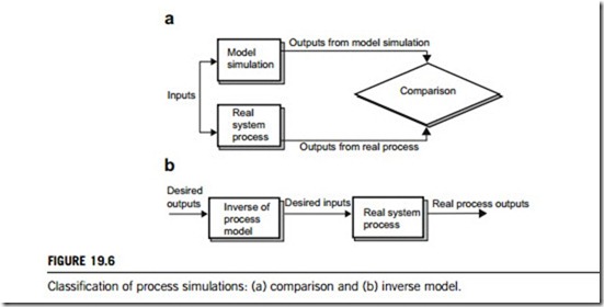
A control simulation is defined as the reproduction of a situation through the use of process models. For complex control projects, simulation of the process is often a necessary measure for validating the process models to develop the most effective control scheme. Many different types are used in product development today, which can be categorized as comparison or inverse models, as illustrated in Figure 19.6.
Modeling and simulation can be aimed at creating controllers for the processes, which is either a software toolkit or an electronic device. The controllers developed are mostly used for performing so-called model-based control, widely applied in industrial applications. The following paragraphs briefly discuss the various algorithms arising from controller designs in model-based control.
(1) Feed-forward control
Feed-forward control can be based on process models. A feed-forward controller has been combined with different feedback controllers; even the ubiquitous three-term proportional-integral-derivative (PID) controllers can be used for this purpose. A proportional-integral controller is optimal for a first- order linear process (expressed with a first-order linear differential equation) without time delays. Similarly, a PID controller is optimal for a second-order linear process without time delays. The modern approach is to determine the settings of the PID controller based on a model of the process, with the settings chosen so that the controlled responses adhere to user specifications. A typical criterion is that the controlled response should have a quarter decay ratio, or it should follow a defined trajectory, or that the closed loop has certain stability properties.
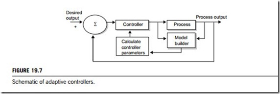
A more elegant technique is to implement the controller within an adaptive framework. Here the parameters of a linear model are updated regularly to reflect current process characteristics. These parameters are in turn used to calculate the settings of the controller, as shown schematically in Figure 19.7. Theoretically, all model-based controllers can be operated in an adaptive mode, but there are instances when the adaptive mechanism may not be fast enough to capture changes in process characteristics due to system nonlinearities. Under such circumstances, the use of a nonlinear model may be more appropriate. Nonlinear time-series, and neural networks, have been used in this context. A nonlinear PID controller may also be automatically tuned, using an appropriate strategy, by posing the problem as an optimization problem. This may be necessary when the nonlinear dynamics of the plant are time-varying. Again, the strategy is to make use of controller settings most appropriate to the current characteristics of the controlled process.
(2) Model predictive control
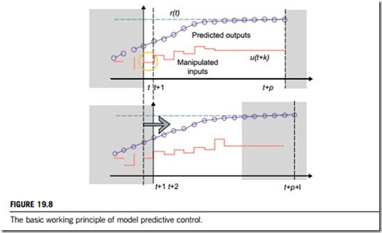
Model predictive control (MPC) is an effective means of dealing with large multivariable constrained control problems. The main idea is to choose the control action by repeatedly solving online an optimal control problem, aiming to minimize a performance criterion over a future horizon, possibly subject
to constraints on the manipulated inputs and outputs. Future behavior is computed according to a model of the plant. Issues arise in guaranteeing closed-loop stability, handling model uncertainty, and reducing online computations.
PID type controllers do not perform well when applied to systems with significant time delays.
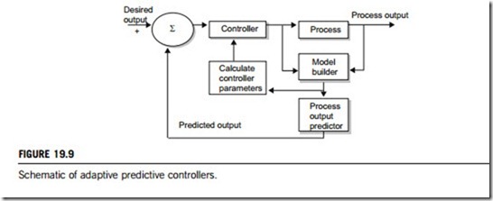
Model predictive control overcomes the debilitating problems of delayed feedback by using predicted future states of the output for control. Figure 19.8 gives the basic principle of model-based predictive control. Currently, some commercial controllers have Smith predictors as programmable blocks, but there are many other strategies with dead-time compensation properties. If there is no time delay, these algorithms usually collapse to the PID form. Predictive controllers can also be embedded within an adaptive framework, and a typical adaptive predictive control structure is shown in Figure 19.9.
(3) Physical-model-based control
Control has always been concerned with generic techniques that can be applied across a range of physical domains. The design of adaptive or nonadaptive controllers for linear systems requires a representation of the system to be controlled. For example, observer and state-feedback designs require a state-space representation, and polynomial designs require a transfer-function representation. These representations are generic in the sense that they can represent linear systems drawn from a range of physical domains, including mechanical, electrical, hydraulic, and thermodynamic. However, at the same time, these representations suffer from being abstractions of physical systems: the very process of abstraction means that system-specific physical details are lost. Both parameters and states of such representations may not be easily related back to the original system parameters. This loss is, perhaps, acceptable at two extremes of knowledge about the system where the system parameters are completely known, or where they are entirely unknown. In the first case, the system can be translated into the representations mentioned above, and the physical system knowledge is translated into, for example, transfer function parameters. In the second case, the system can be deemed to have one of the representations mentioned above and there is no physical system knowledge to be translated. Thus, much of the current body of control achieves a generic coverage of application areas by having a generic representation of the systems to be controlled, which are, however, not well suited to partially known systems.
This suggests an alternative approach that, whilst achieving a generic coverage of application areas, allows the use of particular representations for particular (possibly partially known, possibly nonlinear) systems. Instead of having a generic representation, a generic method, called
meta-modeling has been proposed; it provides a clear conceptual division between structure and parameters, as a basis for this.
(4) Internal models and robust controls
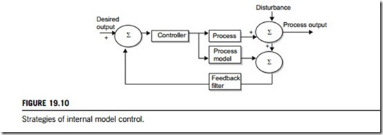
Internal model control systems are characterized by a control device consisting of the controller and of a simulation of the process, the internal model. The internal model loop computes the difference between the outputs of the process and of the internal model, as shown in Figure 19.10. This difference represents the effect of disturbances and of a mismatch of the model. Internal model control devices
have been shown to be robust against disturbances and model mismatch in the case of a linear model of the process. Internal model control characteristics are the consequence of the following properties.
(a) If the process and the controller are (input-output) stable, and if the internal model is perfect, then the control system is stable.
(b) If the process and the controller are stable, if the internal model is perfect, if the controller is the inverse of the internal model, and if there is no disturbance, then perfect control is achieved.
(c) If the controller steady-state gain is equal to the inverse of the internal model steady-state gain, and if the control system is stable with this controller, then offset-free control is obtained for constant set points and output disturbances.
As a consequence of (c) above, if the controller is made of the inverse of the internal model cascaded with a low-pass filter, and if the control system is stable, then offset-free control is obtained for constant inputs, which are set points and output disturbances. Moreover, the filter introduces robustness against a possible mismatch of the internal model, and, though the gain of the control device without the filter is not infinite as in the continuous-time case, its concern is to smooth out rapidly changing inputs. Robust control involves, first, quantifying the uncertainties or errors in a nominal process model, due to nonlinear or time-varying process behavior, for example. If this can be accomplished, we essentially have a description of the process under all possible operating conditions. The next stage involves the design of a controller that will maintain stability as well as achieve specified performance over this range of operating conditions. A controller with this property is said to be robust.
A sensitive controller is required to achieve performance objectives. Unfortunately, such a controller will also be sensitive to process uncertainties and hence suffer from stability problems. On the other hand, a controller that is insensitive to process uncertainties will have poorer performance characteristics in that controlled responses will be sluggish. The robust control problem is therefore formulated as a compromise between achieving performance and ensuring stability under assumed process uncertainties. Uncertainty descriptions are at best very conservative, whereon performance objectives will have to be sacrificed. Moreover, the resulting optimization problem is frequently not well posed. Thus, although robustness is a desirable property, and the theoretical developments and analysis tools are quite mature, application is hindered by the use of daunting mathematics and the lack of a suitable solution procedure.
Nevertheless, underpinning the design of robust controllers is the so-called internal model principle. It states that unless the control strategy contains, either explicitly or implicitly,
a description of the controlled process, then either the performance or stability criterion, or both, will not be achieved. The corresponding internal model control design procedure encapsulates this philosophy and provides for both perfect control and a mechanism to impart robust properties (see Figure 19.10).
