Switch mounting
The majority of switches are panel-mounted, and the methods (such as bush, snap-fit and flange mounting) have already been mentioned. Vhen a large bank of switches is to be available on a panel, there may be a problem of removing the panel for servicing, and a good solution is a sub- frame. The switches are mounted on a sub-panel, with only the operating toggles or other mechanical parts protruding through holes in the main panel, and the sub-panel is attached in only a few places. In this way, only a few bolts need to be removed to allow the main panel to be detached, avoiding the need to remove each switch individually. A few types of switch require specialized mountings – the rotary edge-wheel type, for instance, is very difficult to accommodate. Microswitches in particular do not lend themselves well to panel mounting, and usually require the use of angle brackets. In general, any application involving the use of micro- switches will need some thought as to fixing methods, since the built-in fixings consist only of two holes in the casing of the microswitch that do not permit direct connection to any surface not parallel to the movement of the actuating pin.
Relays
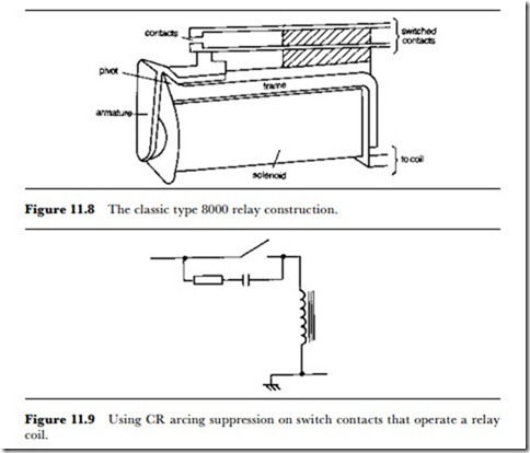
The classical form of relay is illustrated in Figure ll.8. The coil, usually a solenoid, is wound on a former around a core, and a moving armature forms part of the magnetic circuit. Vhen the coil is energized, the armature moves against the opposition of a spring (or the elasticity of a set of leaves carrying the electrical contacts) so as to complete the magnetic circuit. This movement is transmitted to the switch contacts through a non-conducting bar or rod, so that the contacts close, open or change-over
depending on the design of the relay. The contacts are subject to the same limits as those of mechanical switches, but the magnetic operation imposes its own problems of make and break time, contact force and power dissipation. Like so many other electronics components, relays for electronics use have been manufactured in decreasing sizes, and it is even possible to buy relays that are packaged inside a standard TO-5 transistor can.
Since the contact requirements are as for other types of switches, we shall look mainly at the magnetic operation of a relay. The operating coil constitutes an inductor as far as its circuit is concerned, and if this coil is being driven by a transistor then a diode should be used to prevent damage due to the back-EMF when the coil current is switched off. This point is noted in relation to reed relays in Chapter l2. If the relay is operated by a mechanical switch the need for protection is less stringent, but a CR network (Figure ll.9) across the switch contacts is often used to suppress sparking, not least because of the need to reduce electromagnetic impulse interfer- ence. If the relay is used in equipment that incorporates amplification of low-amplitude RF signals, much more thorough radio interference reduction will be needed both across the switch contacts and across the relay contacts.
The specification for a relay will include the permitted range of current or, more commonly, voltage that can be applied to the coil. At the minimum level and below, correct operation cannot be ensured. The relay may hold in at a voltage or current considerably lower than the specified minimum, but cannot pull in its armature if the relay has been off. The maximum rating is due to dissipation, so that exceeding the maximum voltage or current rating will cause overheating, and will also cause more severe contact bounce. The normal rated values that are quoted are usually close to the lower limits, so that a typical percentage tolerance is -8% to +60%. Failure to maintain the correct voltage on a line used to energize a relay can therefore lead to incorrect operation if the voltage falls by a comparatively small amount. For many purposes, using a large reservoir capacitor on such a supply eases problems of maintaining voltage, because if the capacitor can maintain the voltage level for long enough (typically 0.5-l0 ms for small relays) then a drop in voltage of more than 8% will be harmless, since this will still be enough to hold the relay.
The use of a relay as a remote electrically controlled switch is just one aspect of relay use. Relays are used where the use of switches alone would require impossible mechanical interconnections or awkward electrical cabling. They can be placed where a mechanical type of switch could not be reached, in environments where sealed contacts must be used, or where the contacts have to handle voltages or currents that are beyond the range of normal switches. An important feature of almost any type of relay is its electrical isolation between the operating coil and the contacts. For some uses, safety considerations demand the use of relays when a mains (or higher) voltage supply has to be switched by low-voltage equipment with no ground connection. Relays are also used when a sequence of switching has to be carried out, initiated by making contacts on one single switch, or where a safety cut-out is required that will provide isolation from high voltages until reset.
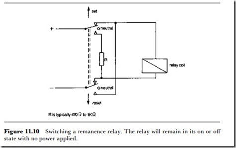
Like switches, relays also exist in special forms. In the latching relay, a mechanical tooth and ratchet will maintain the contacts in a set position. The normal form of relay operates its contacts for as long as current flows in the coil, but a latching relay can be used to hold contacts either made or broken, reversing the action each time current is applied to the coil. A similar action can be obtained without any mechanical complications using a remanence relay, in which the coil current is applied for a controlled time (typically more than l0 ms and less than l min). This magnetizes a core made from an alloy that retains its magnetism after the coil current is switched off. The retained magnetism then holds the armature in place until a reverse current is passed through the coil. The reverse current is usually smaller than the forward current, and a circuit arrangement such as that in Figure ll.l0 is used with a resistor to control the reverse current. A third method of achieving a latching action is to incorporate a permanent magnet into the core path. If the strength of this magnet is
midway between the holding and pull-in levels, then such a magnet cannot operate the relay unless current flows in the correct polarity in the coil. Once the armature has been pulled in, completing the magnetic path, the permanent magnet can maintain this state. To release the relay a lower current has to be applied in the reverse direction.
High sensitivity relays can also be bought off the shelf. These incorporate a transistor and protection diode so as to allow the relay to be operated with a very low current swing (although the voltage swing will be of the order of 0.6-l.2 V). The use of a Darlington pair circuit (Figure ll.ll) allows very low current operation, typically of the order of l00 CIA, to be used. The use of transistor drivers can ensure that the operating voltage and current can be at safe, non-sparking levels, with currents low enough to be no hazard even in biomedical applications.

